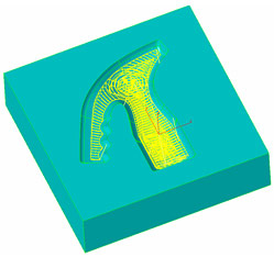
3D Roughing operations using the “Pocketing” toolpath type now also support the “UltraHSM” option, previously only available for 2.5D pocketing. Constant material removal rate is obtained by feedrate optimization and circular cutting passes in combination with radial ramp in/out moves guarantee a continuous toolpath without any sharp corners. This usually reduces machining time and increases tool life by up to 10 times.
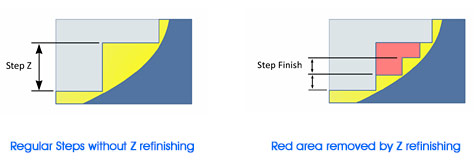
Pocketing and Zig-Zag types of Roughing methods of the 3D-Wizard can now automatically create refinishing Z step passes between two consecutive roughing levels to reduce the resulting steps along the part wall. If “Step Finish” parameter in “Z-Data” section is defined, then these methods use “Step-Z” to calculate the roughing levels each of which is followed by refinishing passes calculated using “Step Finish” parameter. As a result, the remaining steps along the part surface are much smaller, leaving less material to be removed by subsequent finishing operations.
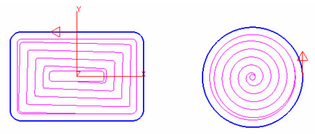
The 2,5D Pocketing cycle now includes the new “Helical” option (see “Cycle Data” tab) to create a helical continuous toolpath, completely avoiding any direct plunge into the material. Below you can see two examples of basic pocket profiles demonstrating nicely the new helical toolpath strategy.
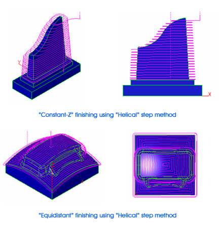
The 3D wizards “Equidistant” and “Constant-Z” finishing methods also provide the new “Helical” step type to create a continuous toolpath which improves surface quality by avoiding marks created by direct step-over moves between finishing passes.
The 3D wizards “Constant-Z” finishing method now supports check surfaces which can be selected to define a machining boundary. The toolpath will then automatically start at the open edge if selected cut surfaces are not closed. In addition, with “Step” type set to “Linear”, one can use the “Plunge Options” to apply any combination of linear or arc ramp moves. The machining direction can be controlled via the “Climb Milling” option.
For 3D wizards “Constant-Z” finishing worksteps, the “Connect” option, located in the “Z-Data” section of the “Tool Info” machining dialog, can be used to create a bi-directional toolpath eliminating rapid-over moves.
Note:
The “Connect” option can only be used in combination with “Step” type set to “Open Surface” in the wizard dialog. If any kind of ramp moves (see “Plunge Options”) are also applied or the machining direction is changed ( see “Climb Milling”), it may be necessary to adjust the “Offset Dir” setting located in the “Cycle Data” machining dialog.
The 3D wizards “Equidistant” and “Constant-Z” finishing option to limit the toolpath by defining surface angle has been completely revised. It now apply limits correctly onto the toolpath itself rather than the surface model as in prior versions.
The 3D wizards “Re-Roughing” method is enhanced to correctly support regions at the open edges of the model.
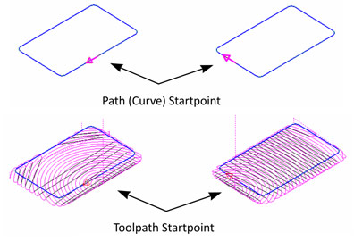
When applying the “Outside-In” option (see “Cycle Data”) to 2D “UltraHSM” pocketing operations, the toolpath now starts at the closest location to the start point of the path (selected curve).
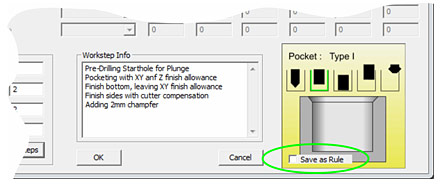
The curve wizard now displays the new “Save as Rule” setting to associate the current curve name with the currently selected machining feature. A rule is established by matching certain section in the curve ID with the selected wizard method. For curves representing holes, this identifier section starts with the letter “D” followed by the hole diameter (format “XXXXD###.###XXXX”). For general shapes any text preceded by the “-“ character (format “XXX-yourtext”) can be defined as the identifier. Curve wizard searches the identifiers of all pre-defined rules in the ID of the current curve and if one detected the method defined by that rule is preselected.
Example:
The current curve is representing some holes of diameter 5.2mm. The name of this curve was manually defined as “Crv5-D5.2-backside”. You then open the curve wizard, select “Holes” category and “Hole-D5.2” from the “Method” list. Before closing the wizard, the “Save as rule” option is activated. EZCAM now associates the string “D5.2” with the method “Hole-D5.2” and saves this information in its INI file. Next time you open the wizard with a curve having “D5.2” in its ID, the “Hole-D5.2” method is automatically preselected. This is especially helpful when using the “Hole Recognition” command (see “Curve” menu) which automatically creates drilling curves with ID’s containing their diameter value preceded by the “D” character.
The “Auto” command button for “Z-Depth” setting (see “Tool Info” dialog) now copies the value from the “Z-Coordinate” entry box if there is no path curve selected or if the selected path is at Z-Surf level.
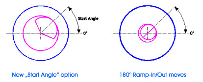
The “Threadmilling” cycle has been updated with several new features. First, it now supports the selection of multiple machining curves by using the „Select Curves“ command (see „Machining“ menu). In addition it is now possible to define any angle between 0 and 359 degrees in 1° steps as the toolpath’s „Start Angle“. Another enhancement is the automatic 180° ramp-in/out move for cases where tool diameter and “Root Diameter” do not leave enough space for regular ramp moves. The pitch applied to these 180° ramp moves is 0,15 x regular pitch.
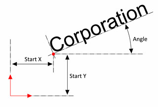
The “Lettering” cycle provides a quick solution to engrave text input by using the simple “Modern” font. Beside some internal modifications a new “Angle” field has been implemented. This allows rotation of the text around the coordinates defined by the “Start X” and “Start Y” settings.
After many years of excellent service, EZCAM’s unique spreadsheet module has been replaced and functionally enhanced to answer various user requests and operating system requirements. Below you’ll find the list of its most important new features.
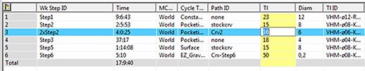
- The content display is improved by use of different colors to highlight current row, column and selected field.
- Columns can be reordered by drag and drop.
- You can hide/show columns in “customize” mode, activated by either pressing “Alt” key or displaying the “Customize buttons” dialog from the “View” menu. Columns to be hidden are then displayed in purple and removed from the table upon exiting customize mode.
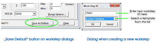
The “
Save Defaults” command, located in the tabbed machining dialogs, can now be used to save the settings of the current workstep as template for subsequent operations. User is prompted for a template ID to save current settings in a “
3dp” (Mill) or “
trn” (Turn) file under that name in predefined subfolders, “
WorkstepTemplateMetric” or “
WorkstepTemplateInch”. If the “
ID” input field is left as “
Default”, then current settings are saved into the “
ezcam.ini” file to be used as “
Default Template”. When creating a new workstep, the ID input dialog now also displays the template list which includes “
Default Template” as the current selection followed by the names of any available templates. If no templates exist this list is not included.
The 2,5D Pocketing cycle now includes the new “Helical” option (see “Cycle Data” tab) to create a helical continuous toolpath, completely avoiding any direct plunge into the material. Below you can see two examples of basic pocket profiles demonstrating nicely the new helical toolpath strategy.
The “Auto” command button for “Z-Depth” setting (see “Tool Info” dialog) now copies the value from the “Z-Coordinate” entry box if there is no path curve selected or if the selected path is at Z-Surf level.
The “Show Toolpath” list found in the “Setup” dialog (see “View” menu) now includes the new “Auto Update” option. This lets the system automatically redraw any 2,5D toolpath whenever a related workstep setting is changed. This removes the need to call “Verify” for toolpath recalculation after every parameter change.
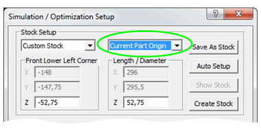
The “Stock Setup” dialog (see “Machining” menu) includes a new list to re-define the “World” origin at the selected location of the box representing the stock limits. When opening the dialog its default setting is “Current Part Origin” followed by the new options “Top Middle”, “Front-Left”, “Back-Left”, “Front-Right” and “Back-Right”. When one of them is selected, the “WORLD” coordinate System is moved to that location instantly.
The “ezcam.ini” initialization file is used to save various settings such as workstep default values, last used filenames, postprocessor, etc. Depending on the current UAC (user account control) setting this file is located directly in the windows main folder, or in a specific user subfolder. EZCAM version 2015 now offers different methods to customize the location of ezcam.ini. Its pathname, for example “c:\windows\ezcam.ini”, can now be a command line argument in the EZCAM program shortcut allowing working with different copies of ezcam.ini. The “Special INI Settings” dialog under “Help” menu has been updated to allow customization of this pathname as well. It can also be changed by directly setting a value for the
registry key: HKEY_CURRENT_USER\Software\EZ-CAM\General\Settings\IniFilename
The “Threadmilling” cycle has been updated with several new features. First, it now supports the selection of multiple machining curves by using the „Select Curves“ command (see „Machining“ menu). In addition it is now possible to define any angle between 0 and 359 degrees in 1° steps as the toolpath’s „Start Angle“. Another enhancement is the automatic 180° ramp-in/out move for cases where tool diameter and “Root Diameter” do not leave enough space for regular ramp moves. The pitch applied to these 180° ramp moves is 0,15 x regular pitch.
The “Lettering” cycle provides a quick solution to engrave text input by using the simple “Modern” font. Beside some internal modifications a new “Angle” field has been implemented. This allows rotation of the text around the coordinates defined by the “Start X” and “Start Y” settings.
The “Check Angle” command (see “View/Check” menu) can now be used to display the angle between two selected surfaces.
Surfaces can now be exported as STL file.
After many years of excellent service, EZCAM’s unique spreadsheet module has been replaced and functionally enhanced to answer various user requests and operating system requirements. Below you’ll find the list of its most important new features.
- The content display is improved by use of different colors to highlight current row, column and selected field.
- Columns can be reordered by drag and drop.
- You can hide/show columns in “customize” mode, activated by either pressing “Alt” key or displaying the “Customize buttons” dialog from the “View” menu. Columns to be hidden are then displayed in purple and removed from the table upon exiting customize mode.
The 2,5D Pocketing cycle now includes the new “Helical” option (see “Cycle Data” tab) to create a helical continuous toolpath, completely avoiding any direct plunge into the material. Below you can see two examples of basic pocket profiles demonstrating nicely the new helical toolpath strategy.
The “Auto” command button for “Z-Depth” setting (see “Tool Info” dialog) now copies the value from the “Z-Coordinate” entry box if there is no path curve selected or if the selected path is at Z-Surf level.
The “Show Toolpath” list found in the “Setup” dialog (see “View” menu) now includes the new “Auto Update” option. This lets the system automatically redraw any 2,5D toolpath whenever a related workstep setting is changed. This removes the need to call “Verify” for toolpath recalculation after every parameter change.
The “Threadmilling” cycle has been updated with several new features. First, it now supports the selection of multiple machining curves by using the „Select Curves“ command (see „Machining“ menu). In addition it is now possible to define any angle between 0 and 359 degrees in 1° steps as the toolpath’s „Start Angle“. Another enhancement is the automatic 180° ramp-in/out move for cases where tool diameter and “Root Diameter” do not leave enough space for regular ramp moves. The pitch applied to these 180° ramp moves is 0,15 x regular pitch.
The “Lettering” cycle provides a quick solution to engrave text input by using the simple “Modern” font. Beside some internal modifications a new “Angle” field has been implemented. This allows rotation of the text around the coordinates defined by the “Start X” and “Start Y” settings.
The simplified user dialogs found in Mill Express have been updated to reflect latest changes in the software. The “Contour” cycles dialog now controls the “Offset Dir.”, “Cutter Comp” and “Lead In/Out” settings and activates/deactivates certain fields based on current selections. Instead of using fixed values for ramp moves it now sets a percentage of the tool diameter as the ramp radius and linear lead length settings. In case cutter compensation on the control is used, this percentage is 60%, for all other cases 10%. This way, it is not necessary any more to change these settings whenever“Tool Diameter” is changed. The “Pocket” and “Face” feature dialogs now also support percentage character input for the “Stepover” setting.
After many years of excellent service, EZCAM’s unique spreadsheet module has been replaced and functionally enhanced to answer various user requests and operating system requirements. Below you’ll find the list of its most important new features.
- The content display is improved by use of different colors to highlight current row, column and selected field.
- Columns can be reordered by drag and drop.
- You can hide/show columns in “customize” mode, activated by either pressing “Alt” key or displaying the “Customize buttons” dialog from the “View” menu. Columns to be hidden are then displayed in purple and removed from the table upon exiting customize mode.
The “
Save Defaults” command, located in the tabbed machining dialogs, can now be used to save the settings of the current workstep as template for subsequent operations. User is prompted for a template ID to save current settings in a “
3dp” (Mill) or “
trn” (Turn) file under that name in predefined subfolders, “
WorkstepTemplateMetric” or “
WorkstepTemplateInch”. If the “
ID” input field is left as “
Default”, then current settings are saved into the “
ezcam.ini” file to be used as “
Default Template”. When creating a new workstep, the ID input dialog now also displays the template list which includes “
Default Template” as the current selection followed by the names of any available templates. If no templates exist this list is not included.
The “Show Toolpath” list found in the “Setup” dialog (see “View” menu) now includes the new “Auto Update” option. This lets the system automatically redraw any 2,5D toolpath whenever a related workstep setting is changed. This removes the need to call “Verify” for toolpath recalculation after every parameter change.
The “Stock Setup” dialog (see “Machining” menu) includes a new list to re-define the “World” origin at the selected location of the box representing the stock limits. When opening the dialog its default setting is “Current Part Origin” followed by the new options “Top Middle”, “Front-Left”, “Back-Left”, “Front-Right” and “Back-Right”. When one of them is selected, the “WORLD” coordinate System is moved to that location instantly.
The “ezcam.ini” initialization file is used to save various settings such as workstep default values, last used filenames, postprocessor, etc. Depending on the current UAC (user account control) setting this file is located directly in the windows main folder, or in a specific user subfolder. EZCAM version 2015 now offers different methods to customize the location of ezcam.ini. Its pathname, for example “c:\windows\ezcam.ini”, can now be a command line argument in the EZCAM program shortcut allowing working with different copies of ezcam.ini. The “Special INI Settings” dialog under “Help” menu has been updated to allow customization of this pathname as well. It can also be changed by directly setting a value for the
registry key: HKEY_CURRENT_USER\Software\EZ-CAM\General\Settings\IniFilename
The “Check Angle” command (see “View/Check” menu) can now be used to display the angle between two selected surfaces.
Surfaces can now be exported as STL file.
After many years of excellent service, EZCAM’s unique spreadsheet module has been replaced and functionally enhanced to answer various user requests and operating system requirements. Below you’ll find the list of its most important new features.
- The content display is improved by use of different colors to highlight current row, column and selected field.
- Columns can be reordered by drag and drop.
- You can hide/show columns in “customize” mode, activated by either pressing “Alt” key or displaying the “Customize buttons” dialog from the “View” menu. Columns to be hidden are then displayed in purple and removed from the table upon exiting customize mode.
The “Show Toolpath” list found in the “Setup” dialog (see “View” menu) now includes the new “Auto Update” option. This lets the system automatically redraw any 2,5D toolpath whenever a related workstep setting is changed. This removes the need to call “Verify” for toolpath recalculation after every parameter change.
The “Punch” and “DIE” wizards have been added some new strategies, which allow greater flexibility when machining sets of multiple parts with different material, thickness or surface finish. The earlier existing strategies always combined “Main”, “Finish” and “Cut-Off” operations in a single workstep. Using this approach it was impossible to use the wizard for multiple parts requiring different number of passes or different conic settings. With the newly added strategies, these cut methods are now available as separate items. For example, you can now define multiple “Punch3” (Main & Finish) worksteps, each with different settings for material, number of passes, or workpiece height. These can be then followed by multiple “Punch4” worksteps to cut them off. Similar changes have been applied to the “DIE” wizard, which now also has separate strategies for “Main”, “Finish” and “Cut-Off” opera-tions/worksteps.
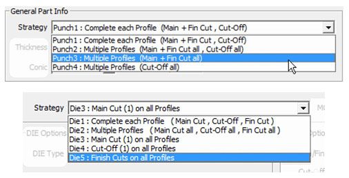
Note:
Once the “Punch3” (Main & Fin) or “DIE3” (Main Cut) for all parts have been defined, the easiest way to create the subsequent final “Cut-Off” or “Finish” worksteps is using the “Spreadsheet” to copy the existing worksteps and then changing the “Strategy” setting to “Cut-Off” or “Finishing”.
The “ezcam.ini” initialization file is used to save various settings such as workstep default values, last used filenames, postprocessor, etc. Depending on the current UAC (user account control) setting this file is located directly in the windows main folder, or in a specific user subfolder. EZCAM version 2015 now offers different methods to customize the location of ezcam.ini. Its pathname, for example “c:\windows\ezcam.ini”, can now be a command line argument in the EZCAM program shortcut allowing working with different copies of ezcam.ini. The “Special INI Settings” dialog under “Help” menu has been updated to allow customization of this pathname as well. It can also be changed by directly setting a value for the
registry key: HKEY_CURRENT_USER\Software\EZ-CAM\General\Settings\IniFilename
The “Check Angle” command (see “View/Check” menu) can now be used to display the angle between two selected surfaces.
Surfaces can now be exported as STL file.
After many years of excellent service, EZCAM’s unique spreadsheet module has been replaced and functionally enhanced to answer various user requests and operating system requirements. Below you’ll find the list of its most important new features.
- The content display is improved by use of different colors to highlight current row, column and selected field.
- Columns can be reordered by drag and drop.
- You can hide/show columns in “customize” mode, activated by either pressing “Alt” key or displaying the “Customize buttons” dialog from the “View” menu. Columns to be hidden are then displayed in purple and removed from the table upon exiting customize mode.
The “
Save Defaults” command, located in the tabbed machining dialogs, can now be used to save the settings of the current workstep as template for subsequent operations. User is prompted for a template ID to save current settings in a “
3dp” (Mill) or “
trn” (Turn) file under that name in predefined subfolders, “
WorkstepTemplateMetric” or “
WorkstepTemplateInch”. If the “
ID” input field is left as “
Default”, then current settings are saved into the “
ezcam.ini” file to be used as “
Default Template”. When creating a new workstep, the ID input dialog now also displays the template list which includes “
Default Template” as the current selection followed by the names of any available templates. If no templates exist this list is not included.
3D Roughing operations using the “Pocketing” toolpath type now also support the “UltraHSM” option, previously only available for 2.5D pocketing. Constant material removal rate is obtained by feedrate optimization and circular cutting passes in combination with radial ramp in/out moves guarantee a continuous toolpath without any sharp corners. This usually reduces machining time and increases tool life by up to 10 times.
Pocketing and Zig-Zag types of Roughing methods of the 3D-Wizard can now automatically create refinishing Z step passes between two consecutive roughing levels to reduce the resulting steps along the part wall. If “Step Finish” parameter in “Z-Data” section is defined, then these methods use “Step-Z” to calculate the roughing levels each of which is followed by refinishing passes calculated using “Step Finish” parameter. As a result, the remaining steps along the part surface are much smaller, leaving less material to be removed by subsequent finishing operations.
The 2,5D Pocketing cycle now includes the new “Helical” option (see “Cycle Data” tab) to create a helical continuous toolpath, completely avoiding any direct plunge into the material. Below you can see two examples of basic pocket profiles demonstrating nicely the new helical toolpath strategy.
The 3D wizards “Equidistant” and “Constant-Z” finishing methods also provide the new “Helical” step type to create a continuous toolpath which improves surface quality by avoiding marks created by direct step-over moves between finishing passes.
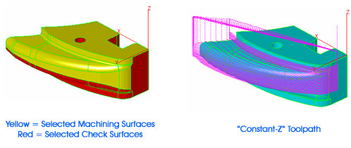
The 3D wizards “Constant-Z” finishing method now supports check surfaces which can be selected to define a machining boundary. The toolpath will then automatically start at the open edge if selected cut surfaces are not closed. In addition, with “Step” type set to “Linear”, one can use the “Plunge Options” to apply any combination of linear or arc ramp moves. The machining direction can be controlled via the “Climb Milling” option.
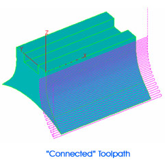
For 3D wizards “Constant-Z” finishing worksteps, the “Connect” option, located in the “Z-Data” section of the “Tool Info” machining dialog, can be used to create a bi-directional toolpath eliminating rapid-over moves.
Note:
The “Connect” option can only be used in combination with “Step” type set to “Open Surface” in the wizard dialog. If any kind of ramp moves (see “Plunge Options”) are also applied or the machining direction is changed ( see “Climb Milling”), it may be necessary to adjust the “Offset Dir” setting located in the “Cycle Data” machining dialog.
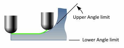
The 3D wizards “Equidistant” and “Constant-Z” finishing option to limit the toolpath by defining surface angle has been completely revised. It now apply limits correctly onto the toolpath itself rather than the surface model as in prior versions.
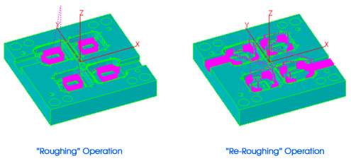
The 3D wizards “Re-Roughing” method is enhanced to correctly support regions at the open edges of the model.
When applying the “Outside-In” option (see “Cycle Data”) to 2D “UltraHSM” pocketing operations, the toolpath now starts at the closest location to the start point of the path (selected curve).
The curve wizard now displays the new “Save as Rule” setting to associate the current curve name with the currently selected machining feature. A rule is established by matching certain section in the curve ID with the selected wizard method. For curves representing holes, this identifier section starts with the letter “D” followed by the hole diameter (format “XXXXD###.###XXXX”). For general shapes any text preceded by the “-“ character (format “XXX-yourtext”) can be defined as the identifier. Curve wizard searches the identifiers of all pre-defined rules in the ID of the current curve and if one detected the method defined by that rule is preselected.
Example:
The current curve is representing some holes of diameter 5.2mm. The name of this curve was manually defined as “Crv5-D5.2-backside”. You then open the curve wizard, select “Holes” category and “Hole-D5.2” from the “Method” list. Before closing the wizard, the “Save as rule” option is activated. EZCAM now associates the string “D5.2” with the method “Hole-D5.2” and saves this information in its INI file. Next time you open the wizard with a curve having “D5.2” in its ID, the “Hole-D5.2” method is automatically preselected. This is especially helpful when using the “Hole Recognition” command (see “Curve” menu) which automatically creates drilling curves with ID’s containing their diameter value preceded by the “D” character.
The “Auto” command button for “Z-Depth” setting (see “Tool Info” dialog) now copies the value from the “Z-Coordinate” entry box if there is no path curve selected or if the selected path is at Z-Surf level.
The “Show Toolpath” list found in the “Setup” dialog (see “View” menu) now includes the new “Auto Update” option. This lets the system automatically redraw any 2,5D toolpath whenever a related workstep setting is changed. This removes the need to call “Verify” for toolpath recalculation after every parameter change.
The “Stock Setup” dialog (see “Machining” menu) includes a new list to re-define the “World” origin at the selected location of the box representing the stock limits. When opening the dialog its default setting is “Current Part Origin” followed by the new options “Top Middle”, “Front-Left”, “Back-Left”, “Front-Right” and “Back-Right”. When one of them is selected, the “WORLD” coordinate System is moved to that location instantly.
The “ezcam.ini” initialization file is used to save various settings such as workstep default values, last used filenames, postprocessor, etc. Depending on the current UAC (user account control) setting this file is located directly in the windows main folder, or in a specific user subfolder. EZCAM version 2015 now offers different methods to customize the location of ezcam.ini. Its pathname, for example “c:\windows\ezcam.ini”, can now be a command line argument in the EZCAM program shortcut allowing working with different copies of ezcam.ini. The “Special INI Settings” dialog under “Help” menu has been updated to allow customization of this pathname as well. It can also be changed by directly setting a value for the
registry key: HKEY_CURRENT_USER\Software\EZ-CAM\General\Settings\IniFilename
The “Threadmilling” cycle has been updated with several new features. First, it now supports the selection of multiple machining curves by using the „Select Curves“ command (see „Machining“ menu). In addition it is now possible to define any angle between 0 and 359 degrees in 1° steps as the toolpath’s „Start Angle“. Another enhancement is the automatic 180° ramp-in/out move for cases where tool diameter and “Root Diameter” do not leave enough space for regular ramp moves. The pitch applied to these 180° ramp moves is 0,15 x regular pitch.
The “Lettering” cycle provides a quick solution to engrave text input by using the simple “Modern” font. Beside some internal modifications a new “Angle” field has been implemented. This allows rotation of the text around the coordinates defined by the “Start X” and “Start Y” settings.
The simplified user dialogs found in Mill Express have been updated to reflect latest changes in the software. The “Contour” cycles dialog now controls the “Offset Dir.”, “Cutter Comp” and “Lead In/Out” settings and activates/deactivates certain fields based on current selections. Instead of using fixed values for ramp moves it now sets a percentage of the tool diameter as the ramp radius and linear lead length settings. In case cutter compensation on the control is used, this percentage is 60%, for all other cases 10%. This way, it is not necessary any more to change these settings whenever“Tool Diameter” is changed. The “Pocket” and “Face” feature dialogs now also support percentage character input for the “Stepover” setting.
The “Punch” and “DIE” wizards have been added some new strategies, which allow greater flexibility when machining sets of multiple parts with different material, thickness or surface finish. The earlier existing strategies always combined “Main”, “Finish” and “Cut-Off” operations in a single workstep. Using this approach it was impossible to use the wizard for multiple parts requiring different number of passes or different conic settings. With the newly added strategies, these cut methods are now available as separate items. For example, you can now define multiple “Punch3” (Main & Finish) worksteps, each with different settings for material, number of passes, or workpiece height. These can be then followed by multiple “Punch4” worksteps to cut them off. Similar changes have been applied to the “DIE” wizard, which now also has separate strategies for “Main”, “Finish” and “Cut-Off” opera-tions/worksteps.
Note:
Once the “Punch3” (Main & Fin) or “DIE3” (Main Cut) for all parts have been defined, the easiest way to create the subsequent final “Cut-Off” or “Finish” worksteps is using the “Spreadsheet” to copy the existing worksteps and then changing the “Strategy” setting to “Cut-Off” or “Finishing”.
The “Check Angle” command (see “View/Check” menu) can now be used to display the angle between two selected surfaces.
Surfaces can now be exported as STL file.