The new “
Stock Milling” option found on the “
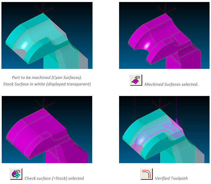
3D Wizard” dialog now gives users two options of how to handle any selected check surfaces. If unchecked, check surfaces define the area that should be avoided by the toolpath. If checked, check surfaces represent the stock model which has to be removed.
Refinishing operations now automatically combine “
Equidistant” and “
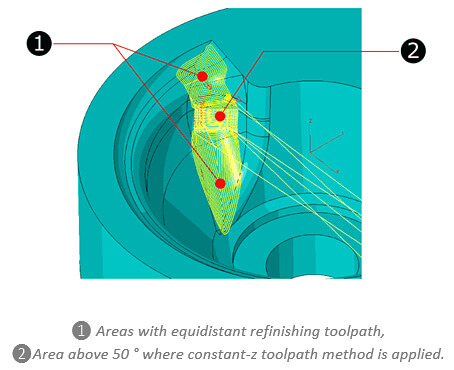
Constant-Z” toolpath types. By using the “
Surface Angle” setting, the user defines the angular limit that is machined using the “
Equidistant” method. For example, by setting surface angle to “0-50” degrees, all areas up to 50° are refinished using the “
Equidistant” method while the rest, up to 90° is machined using the “
Constant-Z” method. Please note, that the lower value of the “
Surface Angle” setting is always ignored and regarded as being “0”.
The 3D-Wizard’s “
Equidistant” and “
Constant-Z” finishing methods now support the use of tools with draft angle defined by the tool angle setting.
If the “
Outside-in” option is checked, any “
3D-Wizard” roughing operation tries to detect open edges along the selected surfaces. If any detected, the toolpath for every Z level pass starts at a plunge location using “
Step-Over” distance away from the open edge.
A new “
Additional Side Allowance” setting is now available for “
3D-Wizard” roughing and finishing (Constant-Z & Equidistant) operations. This enables users to give the system a separate XY finish allowance, regardless of any surface “
Finish Allowance“.
The task of finishing flat areas of a 3D model has been optimized. When “
Equidistant” finishing is used in combination with the “
Outside-In” option and a “
Surface Angle” set to “0” (= only flat areas), the toolpath automatically starts at any open edge that is detected.
By using the new “
Save Defaults” button on the 3D wizard dialog, all current settings can be saved as templates for future use. When creating a new wizard workstep, the workstep ID dialog provides a list box, offering all available wizard templates for selection.
When using the “
Variable Step” option for “
Constant-Z” finishing operations, the applied Z-Step per pass is calculated by the system, based on the specified “
Scallop Height” for the resulting surface. Sometimes, especially along completely vertical surface areas, this resulted in step sizes that exceeded the tools machining capabilities. To avoid this, the new “
Max. Step” settings now allows to set a maximum step value to avoid this.
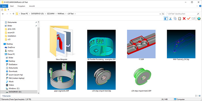
The EZCAM v2017 setup automatically installs a new DLL that allows the Windows operating system to display thumbnail icons with preview images inside its native file explorer. In addition, the preview image is now stored inside EZCAM’s own EZ-MILL (*.3DP) and EZ-TURN (*.TRN) part files. In comparison to earlier EZCAM versions, which stored the preview images as separate files, the new method ensures preview availability even when files are copied over non-windows networks and systems.
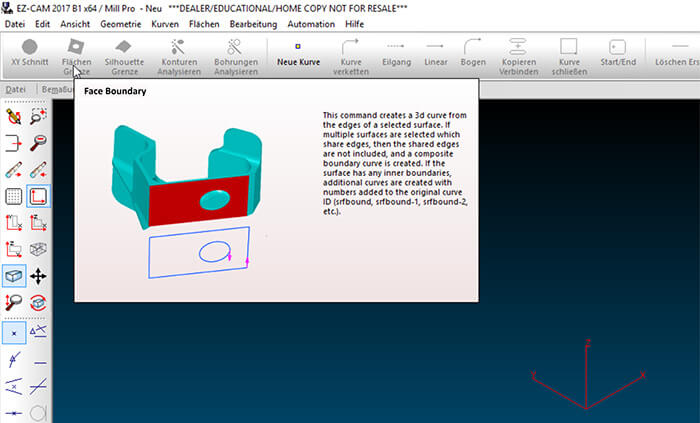
To further improve usability, the tooltips for command buttons now include videos, graphics and multiline text. Especially new or non-regular users will benefit from this fast and more comprehensive help. At the same time, these tooltips have a little delay time build in, so that workflow for experienced users will not be affected.
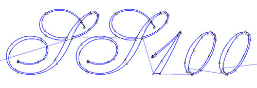
When importing data in EPS (
Encapsulated
Post
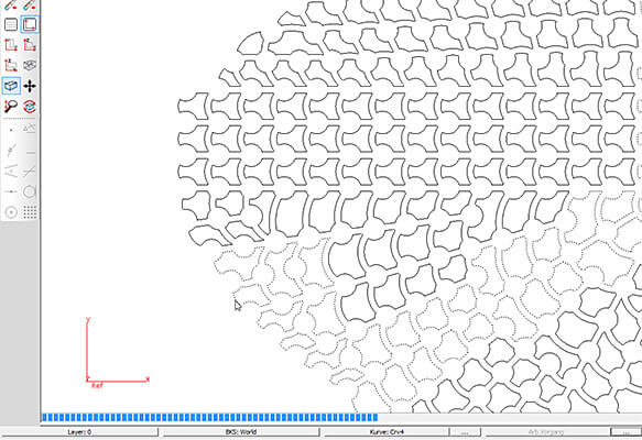
Script) format, curved profiles were often converted into tiny linear moves, increasing file size and making machining more difficult. In addition, this also had negative effects on the profiles visual quality. To improve this, EPS data imported via the “
File Open” command is now automatically optimized into tangent arcs and line entities where ever possible. The graphic below represents the reduced number of curve entities in an imported and optimized EPS file.
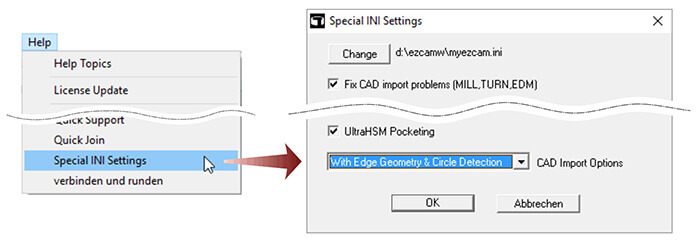
When importing CAD data (STEP, Parasolid, Solidworks, etc.), a three step process is started. First, all surface data is converted into corresponding EZCAM entities. Second, boundary geometry is created for all surfaces. In addition, the system checks boundary quality of adjacent surfaces to prevent double geometry creation. In the third and final step, the system tries to detect arcs or lines that represent full circles and converts them into circle entities. Now each of these steps roughly uses one third of the total import time. To improve performance, the last two steps (geometry creation & circle detection) can be disabled. Both can be executed later by using the new “
Surface Edge Geometry” command, found in the “
Geometry” menu. Another benefit is the reduced amount of data to be hold in memory after import. This greatly improves general handling performance and makes it for example easier to extract the part to be machined from a complete CAD assembly.
Some commands (Translate, Move, Rotate, Mirror, Scale) found in the “
Edit” menu require a special sequence to be followed. Depending on the command you need to select points or insert values such as translation distances or scale factors. Once this is done, the affected entities are selected. The new toggle “Select Entities First” optionally reverses this process. You can first select the entities, then handle the remaining data as required. Many users may find this sequence easier to follow and should therefore be able to increase their productivity.
The EZCAM core and related import libraries have been updated to allow Solidworks 2017 SLDPRT files import. However, this functionality is only available for 64-Bit EZCAM modules.
Due to various requests, the curve “
Chain” command has been updated. Beside the fact that the number of entities to be chained is now unlimited, this command saw several improvements regarding visual feedback during the chaining process. Especially when chaining multiple profiles, the system now gives continuous feedback by highlighting already chained blocks on the screen. In addition, a progress bar is displayed at the bottom of the screen, indicating that the process is still ongoing.
The “
Post Process” dialog received a new button to directly load the current postprocessor into the corresponding postprocessor editor, MBuild for MILL and TBuild for TURN.
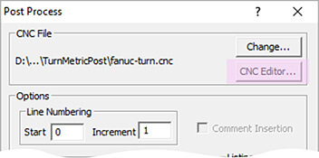
CAUTION
Great care must be taken whenever modifying a postprocessor. Always check the resulting NC code with dry-runs to avoid potential damage to the machine. Alternatively contact EZCAM support for help or advice.
The EZCAM v2017 setup automatically installs a new DLL that allows the Windows operating system to display thumbnail icons with preview images inside its native file explorer. In addition, the preview image is now stored inside EZCAM’s own EZ-MILL (*.3DP) and EZ-TURN (*.TRN) part files. In comparison to earlier EZCAM versions, which stored the preview images as separate files, the new method ensures preview availability even when files are copied over non-windows networks and systems.
To further improve usability, the tooltips for command buttons now include videos, graphics and multiline text. Especially new or non-regular users will benefit from this fast and more comprehensive help. At the same time, these tooltips have a little delay time build in, so that workflow for experienced users will not be affected.
When importing data in EPS (
Encapsulated
Post
Script) format, curved profiles were often converted into tiny linear moves, increasing file size and making machining more difficult. In addition, this also had negative effects on the profiles visual quality. To improve this, EPS data imported via the “
File Open” command is now automatically optimized into tangent arcs and line entities where ever possible. The graphic below represents the reduced number of curve entities in an imported and optimized EPS file.
When importing CAD data (STEP, Parasolid, Solidworks, etc.), a three step process is started. First, all surface data is converted into corresponding EZCAM entities. Second, boundary geometry is created for all surfaces. In addition, the system checks boundary quality of adjacent surfaces to prevent double geometry creation. In the third and final step, the system tries to detect arcs or lines that represent full circles and converts them into circle entities. Now each of these steps roughly uses one third of the total import time. To improve performance, the last two steps (geometry creation & circle detection) can be disabled. Both can be executed later by using the new “
Surface Edge Geometry” command, found in the “
Geometry” menu. Another benefit is the reduced amount of data to be hold in memory after import. This greatly improves general handling performance and makes it for example easier to extract the part to be machined from a complete CAD assembly.
Some commands (Translate, Move, Rotate, Mirror, Scale) found in the “
Edit” menu require a special sequence to be followed. Depending on the command you need to select points or insert values such as translation distances or scale factors. Once this is done, the affected entities are selected. The new toggle “Select Entities First” optionally reverses this process. You can first select the entities, then handle the remaining data as required. Many users may find this sequence easier to follow and should therefore be able to increase their productivity.
The EZCAM core and related import libraries have been updated to allow Solidworks 2017 SLDPRT files import. However, this functionality is only available for 64-Bit EZCAM modules.
Due to various requests, the curve “
Chain” command has been updated. Beside the fact that the number of entities to be chained is now unlimited, this command saw several improvements regarding visual feedback during the chaining process. Especially when chaining multiple profiles, the system now gives continuous feedback by highlighting already chained blocks on the screen. In addition, a progress bar is displayed at the bottom of the screen, indicating that the process is still ongoing.
The “
Post Process” dialog received a new button to directly load the current postprocessor into the corresponding postprocessor editor, MBuild for MILL and TBuild for TURN.
CAUTION
Great care must be taken whenever modifying a postprocessor. Always check the resulting NC code with dry-runs to avoid potential damage to the machine. Alternatively contact EZCAM support for help or advice.
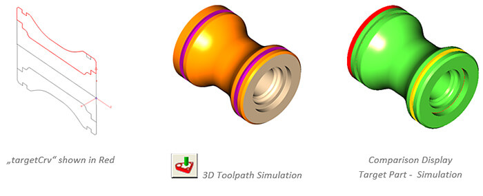
When using the “
Stock & Optimization Setup – Create Uncut Solids” option to compare the as-cut verification model to the original CAD model, a so called “
Target Part” representing the final 3D model of the part needs to be defined. Usually this is done by a single STL surface named “
targetsrf“. New in TURN v2017 is the option to define the target part in form of a simple 2D curve named “
targetCrv“. This curve represents a cross sectional profile that is automatically converted to a target part model by 360° rotation around World Z axis.
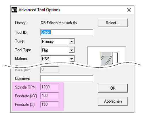
The “
Advanced Tool Options” dialog, used in all live-tool cycles, has been updated to support the default settings for feedrate & speed, retrieved from the current live-tool tool database.
The standard tool library that is shipped with all EZ-TURN modules has been extended with many new tools and tool holders.
The EZCAM v2017 setup automatically installs a new DLL that allows the Windows operating system to display thumbnail icons with preview images inside its native file explorer. In addition, the preview image is now stored inside EZCAM’s own EZ-MILL (*.3DP) and EZ-TURN (*.TRN) part files. In comparison to earlier EZCAM versions, which stored the preview images as separate files, the new method ensures preview availability even when files are copied over non-windows networks and systems.
To further improve usability, the tooltips for command buttons now include videos, graphics and multiline text. Especially new or non-regular users will benefit from this fast and more comprehensive help. At the same time, these tooltips have a little delay time build in, so that workflow for experienced users will not be affected.
When importing data in EPS (
Encapsulated
Post
Script) format, curved profiles were often converted into tiny linear moves, increasing file size and making machining more difficult. In addition, this also had negative effects on the profiles visual quality. To improve this, EPS data imported via the “
File Open” command is now automatically optimized into tangent arcs and line entities where ever possible. The graphic below represents the reduced number of curve entities in an imported and optimized EPS file.
When importing CAD data (STEP, Parasolid, Solidworks, etc.), a three step process is started. First, all surface data is converted into corresponding EZCAM entities. Second, boundary geometry is created for all surfaces. In addition, the system checks boundary quality of adjacent surfaces to prevent double geometry creation. In the third and final step, the system tries to detect arcs or lines that represent full circles and converts them into circle entities. Now each of these steps roughly uses one third of the total import time. To improve performance, the last two steps (geometry creation & circle detection) can be disabled. Both can be executed later by using the new “
Surface Edge Geometry” command, found in the “
Geometry” menu. Another benefit is the reduced amount of data to be hold in memory after import. This greatly improves general handling performance and makes it for example easier to extract the part to be machined from a complete CAD assembly.
Some commands (Translate, Move, Rotate, Mirror, Scale) found in the “
Edit” menu require a special sequence to be followed. Depending on the command you need to select points or insert values such as translation distances or scale factors. Once this is done, the affected entities are selected. The new toggle “Select Entities First” optionally reverses this process. You can first select the entities, then handle the remaining data as required. Many users may find this sequence easier to follow and should therefore be able to increase their productivity.
The EZCAM core and related import libraries have been updated to allow Solidworks 2016 SLDPRT files import. However, this functionality is only available for 64-Bit EZCAM modules.
Due to various requests, the curve “
Chain” command has been updated. Beside the fact that the number of entities to be chained is now unlimited, this command saw several improvements regarding visual feedback during the chaining process. Especially when chaining multiple profiles, the system now gives continuous feedback by highlighting already chained blocks on the screen. In addition, a progress bar is displayed at the bottom of the screen, indicating that the process is still ongoing.
The “
Post Process” dialog received a new button to directly load the current postprocessor into the corresponding postprocessor editor, MBuild for MILL and TBuild for TURN.
CAUTION
Great care must be taken whenever modifying a postprocessor. Always check the resulting NC code with dry-runs to avoid potential damage to the machine. Alternatively contact EZCAM support for help or advice.
The new “
Punch Special” option was added to the “
Autostart for all Curves” function dialog, found in the “
Automation” menu. Originally this command only added “
Lead In/Out” moves along the outside (Punch) or inside (Die) of all visible curves, including any appended sub profiles. The new “
Punch Special” feature now always places the start point of the next profile in-side the previous profiles (already cut & removed) loop.
The use of technology data files in combination with the DIE wizard has been revised to fully support correct assignment of cutting data to the various DIE sections (Conic1, Land, Conic2).
Depending on the selected “
DIE” and “
Sequence” type, the corresponding cutting height is calculated and displayed on the “
Set Technology Data” dialog. According to the displayed height, the “
Calculate” button now retrieves the correct conditions for each section.
The “
Return Distance” setting found on the “
Cycle Data” dialog is now also available for XYUV machining operations. At the end of the second pass, the wire usually moves back all the way to the original start point of the curve. When applying more than 2 passes, this behavior is unnecessary and time consuming. Therefore, if “
Return Distance” is set, the system retracts only by this value, before continuing with the third pass.
When importing CAD data (STEP, Parasolid, Solidworks, etc.), a three step process is started. First, all surface data is converted into corresponding EZCAM entities. Second, boundary geometry is created for all surfaces. In addition, the system checks boundary quality of adjacent surfaces to prevent double geometry creation. In the third and final step, the system tries to detect arcs or lines that represent full circles and converts them into circle entities. Now each of these steps roughly uses one third of the total import time. To improve performance, the last two steps (geometry creation & circle detection) can be disabled. Both can be executed later by using the new “
Surface Edge Geometry” command, found in the “
Geometry” menu. Another benefit is the reduced amount of data to be hold in memory after import. This greatly improves general handling performance and makes it for example easier to extract the part to be machined from a complete CAD assembly.
The EZCAM v2017 setup automatically installs a new DLL that allows the Windows operating system to display thumbnail icons with preview images inside its native file explorer. In addition, the preview image is now stored inside EZCAM’s own EZ-MILL (*.3DP) and EZ-TURN (*.TRN) part files. In comparison to earlier EZCAM versions, which stored the preview images as separate files, the new method ensures preview availability even when files are copied over non-windows networks and systems.
To further improve usability, the tooltips for command buttons now include videos, graphics and multiline text. Especially new or non-regular users will benefit from this fast and more comprehensive help. At the same time, these tooltips have a little delay time build in, so that workflow for experienced users will not be affected.
The new “
Stock Milling” option found on the “
3D Wizard” dialog now gives users two options of how to handle any selected check surfaces. If unchecked, check surfaces define the area that should be avoided by the toolpath. If checked, check surfaces represent the stock model which has to be removed.
Refinishing operations now automatically combine “
Equidistant” and “
Constant-Z” toolpath types. By using the “
Surface Angle” setting, the user defines the angular limit that is machined using the “
Equidistant” method. For example, by setting surface angle to “0-50” degrees, all areas up to 50° are refinished using the “
Equidistant” method while the rest, up to 90° is machined using the “
Constant-Z” method. Please note, that the lower value of the “
Surface Angle” setting is always ignored and regarded as being “0”.
The 3D-Wizard’s “
Equidistant” and “
Constant-Z” finishing methods now support the use of tools with draft angle defined by the tool angle setting.
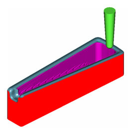
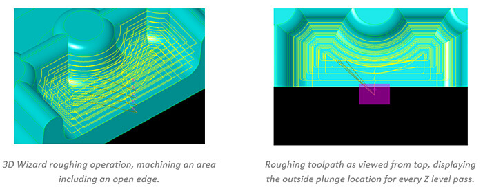
If the “
Outside-in” option is checked, any “
3D-Wizard” roughing operation tries to detect open edges along the selected surfaces. If any detected, the toolpath for every Z level pass starts at a plunge location using “
Step-Over” distance away from the open edge.
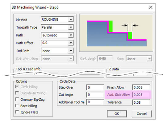
A new “
Additional Side Allowance” setting is now available for “
3D-Wizard” roughing and finishing (Constant-Z & Equidistant) operations. This enables users to give the system a separate XY finish allowance, regardless of any surface “
Finish Allowance“.
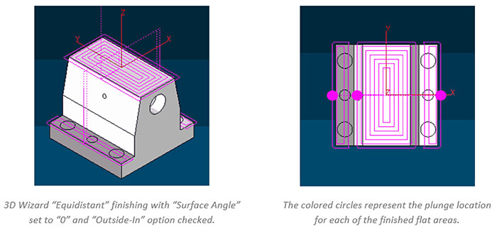
The task of finishing flat areas of a 3D model has been optimized. When “
Equidistant” finishing is used in combination with the “
Outside-In” option and a “
Surface Angle” set to “0” (= only flat areas), the toolpath automatically starts at any open edge that is detected.
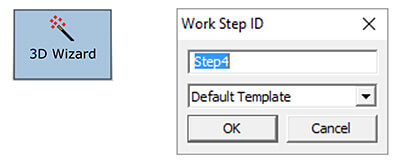
By using the new “
Save Defaults” button on the 3D wizard dialog, all current settings can be saved as templates for future use. When creating a new wizard workstep, the workstep ID dialog provides a list box, offering all available wizard templates for selection.
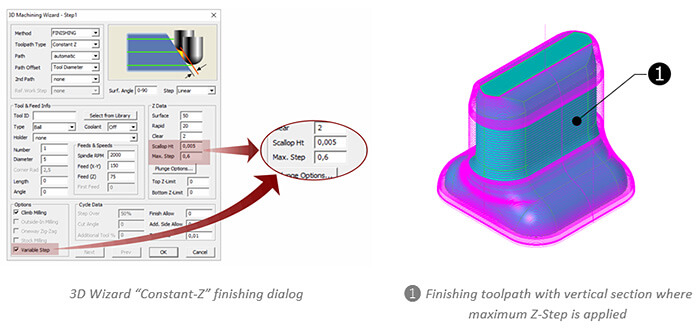
When using the “
Variable Step” option for “
Constant-Z” finishing operations, the applied Z-Step per pass is calculated by the system, based on the specified “
Scallop Height” for the resulting surface. Sometimes, especially along completely vertical surface areas, this resulted in step sizes that exceeded the tools machining capabilities. To avoid this, the new “
Max. Step” settings now allows to set a maximum step value to avoid this.
When importing data in EPS (
Encapsulated
Post
Script) format, curved profiles were often converted into tiny linear moves, increasing file size and making machining more difficult. In addition, this also had negative effects on the profiles visual quality. To improve this, EPS data imported via the “
File Open” command is now automatically optimized into tangent arcs and line entities where ever possible. The graphic below represents the reduced number of curve entities in an imported and optimized EPS file.
When importing CAD data (STEP, Parasolid, Solidworks, etc.), a three step process is started. First, all surface data is converted into corresponding EZCAM entities. Second, boundary geometry is created for all surfaces. In addition, the system checks boundary quality of adjacent surfaces to prevent double geometry creation. In the third and final step, the system tries to detect arcs or lines that represent full circles and converts them into circle entities. Now each of these steps roughly uses one third of the total import time. To improve performance, the last two steps (geometry creation & circle detection) can be disabled. Both can be executed later by using the new “
Surface Edge Geometry” command, found in the “
Geometry” menu. Another benefit is the reduced amount of data to be hold in memory after import. This greatly improves general handling performance and makes it for example easier to extract the part to be machined from a complete CAD assembly.
Some commands (Translate, Move, Rotate, Mirror, Scale) found in the “
Edit” menu require a special sequence to be followed. Depending on the command you need to select points or insert values such as translation distances or scale factors. Once this is done, the affected entities are selected. The new toggle “Select Entities First” optionally reverses this process. You can first select the entities, then handle the remaining data as required. Many users may find this sequence easier to follow and should therefore be able to increase their productivity.
The EZCAM core and related import libraries have been updated to allow Solidworks 2017 SLDPRT files import. However, this functionality is only available for 64-Bit EZCAM modules.
Due to various requests, the curve “
Chain” command has been updated. Beside the fact that the number of entities to be chained is now unlimited, this command saw several improvements regarding visual feedback during the chaining process. Especially when chaining multiple profiles, the system now gives continuous feedback by highlighting already chained blocks on the screen. In addition, a progress bar is displayed at the bottom of the screen, indicating that the process is still ongoing.
The “
Post Process” dialog received a new button to directly load the current postprocessor into the corresponding postprocessor editor, MBuild for MILL and TBuild for TURN.
CAUTION
Great care must be taken whenever modifying a postprocessor. Always check the resulting NC code with dry-runs to avoid potential damage to the machine. Alternatively contact EZCAM support for help or advice.
When using the “
Stock & Optimization Setup – Create Uncut Solids” option to compare the as-cut verification model to the original CAD model, a so called “
Target Part” representing the final 3D model of the part needs to be defined. Usually this is done by a single STL surface named “
targetsrf“. New in TURN v2017 is the option to define the target part in form of a simple 2D curve named “
targetCrv“. This curve represents a cross sectional profile that is automatically converted to a target part model by 360° rotation around World Z axis.
The “
Advanced Tool Options” dialog, used in all live-tool cycles, has been updated to support the default settings for feedrate & speed, retrieved from the current live-tool tool database.
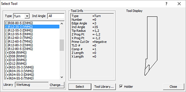
The standard tool library that is shipped with all EZ-TURN modules has been extended with many new tools and tool holders.
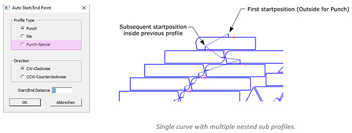
The new “
Punch Special” option was added to the “
Autostart for all Curves” function dialog, found in the “
Automation” menu. Originally this command only added “
Lead In/Out” moves along the outside (Punch) or inside (Die) of all visible curves, including any appended sub profiles. The new “
Punch Special” feature now always places the start point of the next profile in-side the previous profiles (already cut & removed) loop.
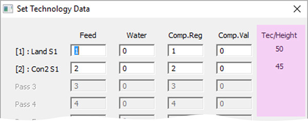
The use of technology data files in combination with the DIE wizard has been revised to fully support correct assignment of cutting data to the various DIE sections (Conic1, Land, Conic2).
Depending on the selected “
DIE” and “
Sequence” type, the corresponding cutting height is calculated and displayed on the “
Set Technology Data” dialog. According to the displayed height, the “
Calculate” button now retrieves the correct conditions for each section.
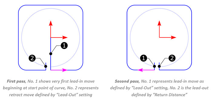
The “
Return Distance” setting found on the “
Cycle Data” dialog is now also available for XYUV machining operations. At the end of the second pass, the wire usually moves back all the way to the original start point of the curve. When applying more than 2 passes, this behavior is unnecessary and time consuming. Therefore, if “
Return Distance” is set, the system retracts only by this value, before continuing with the third pass.