


MILL / TURN
– All OpenGL Graphics – EZCAM’s graphics system has been completely revised with extended OpenGL support which increases usability and ensures flawless integration into current Windows 7 environment. Other benefits include:
- Increased robustness under different graphics card and driver configurations.
- Better compatibility with latest graphics features such as Windows Aero (the graphical user interface and default theme in most editions of Windows Vista and Windows 7).
- Increased display performance, resulting in faster screen updates.
 Version 18 Version 18 |
 Version 19 Version 19 |
- Greatly improved display management when working with toolpaths for multiple worksteps.
- Greatly enhanced curve display in shaded mode.
 |
|
- The entity selection list has been updated for increased performance when working with large number of entities.
- New background color option – “Gradient” – with upper and lower color selection, for a better work environment.
MILL
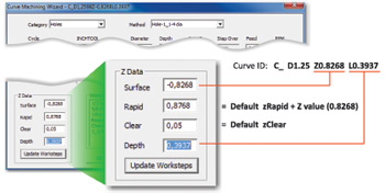
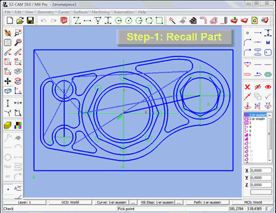
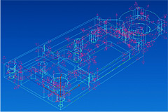
-Automatic Hole Recognition– The new command analyzes an imported 3D model with respect to the XY plane of the current coordinate system and automatically chains circles in the part as separate curves according to diameter, z-surf and depth of the detected holes. The integrated gouge check capability eliminates holes that are unreachable (such as blind holes at the bottom of the part) and also sets the type of moves connecting the circles to ensure safe tool retract levels. The curve ID assigned during the process follows a specific rule: “D” + hole diameter, “Z” + top Z level and “L” + hole depth.
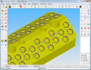
The real gain in performance is achieved when curves generated by this new command are used in association with the updated curve wizard that was first introduced in EZCAM v18. It copies the Z-Surf and Z-Depth values included in the curve ID into the corresponding fields of the combo worksteps.
| Selected Curve
|
Curve wizard with data copied from curve ID
 |
MILL / MILL Express / TURN
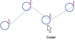
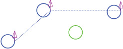
– Delete single Holes from drilling curves – “Toggle rapid” curve command has been modified to delete the selected full circle move and connect previous circle to the next one..
|
Select circular entity (hole) to be removed
 |
Curve with removed hole
 |
MILL / MILL Express / TURN
– New Role for Stock Setup “Save Simulation” Option – EZCAM saves the simulation stage at the completion of each workstep. When Simulation view is active, changing the selection in the workstep listbox with the mouse or the up/down arrow keys resets the simulation model to the corresponding stage. “Preview 3D” and “Rapid Cut” commands start simulating from the end of the current workstep. If the CAD view is active and you want to start simulation from a specific workstep, use Recall Part command to view the simulation at the end of that workstep, and then start simulation.
MILL / MILL Express
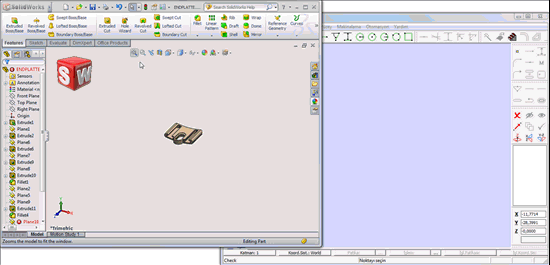
– Update From SolidWorks Model – This command in the “Edit” menu transfers the model currently active in SolidWorks workspace into the current EZCAM session. For each SolidWorks face, a separate surface is generated, ready to be machined using SolidWorks original facet information, resulting in better machining quality than possible using an imported model. Edge geometry is created, without any overlapping elements, allowing Chain command to be used as a robust alternate method for creating machining paths. This will enable EZ-MILL Express, too, to be a partner module for SolidWorks. With the surfaces generated, face Boundary command will create boundary information that is accurate and 100% compatible with SolidWorks. Repeating the “Update From SolidWorks Model” command will apply any changes in the active SolidWorks model to the current EZCAM window.
MILL Pro / 3D Machining Wizard
– Rest Machining with Boundaries – The rest machining option now allows the selection of a curve to be used as toolpath boundary. Any rest machining process can further be limited to specific areas of the model which would optimize the operation by avoiding areas of the part that do not need rest machining.
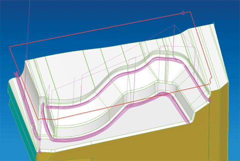 Red Curve = Selected Boundary
In this example the boundary was used to prevent the tool from entering the outside areas of the part.
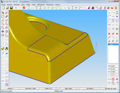
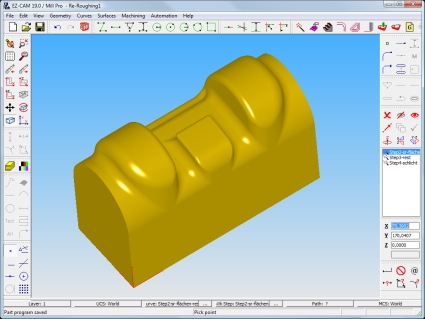
MILL Pro / 3D Machining Wizard
– Re-Roughing updated – The refined re-roughing option now ensures that the tool plunges from the previous z-level instead of from Z-Surf. This greatly reduces slow Z feedrate moves and saves up to 75% of the total cutting time for the rest machining operation.
MILL / TURN
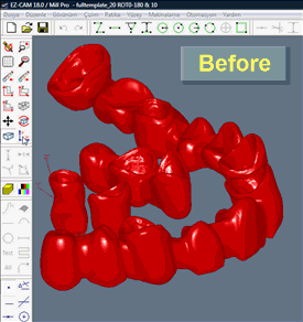
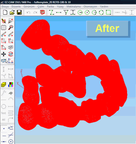
– Curve / Surface direction display – The setting to display curve/surface direction arrows (see “View/Setup” dialog) has been updated. The listbox now includes options to display only curve directions or to display both curve and surface directions.
|
Curve direction display only
 |
Curve & Surface direction display
 |
MILL / TURN
– Motion Record Dialog – Motion record dialog is now “modeless” to allow access to viewing commands, as well as graphical selection of the current move, without the dialog’s needing to be closed and reopened. This feature enables very efficient creation of 3D curves via inputting of Z values into the dialog.
MILL / TURN / EDM
– Updated CAD Import Filters – The integrated import filters have been updated to support latest SolidWorks 2011 (SLDPRT) and AutoCAD 2012 (DWG) file formats.
MILL / MILL Express
– Thread Milling / Repeat Transformations – Thread Milling worksteps supports the use of “Repeat transformation” options located on the “Verification” tab of the Workstep Data dialog.
MILL / TURN / EDM
– Importing CAD Assemblies – Some CAD files may contain complete assemblies with multiple solids instead of only the single part to be machined. EZCAM import filters have been updated to detect single solids and to place them into different layers with the solids name. In addition all surfaces of a particular solid have the solids ID as part of their ID (Solid1-Srf1, Solid1-Srf2, etc.)..