


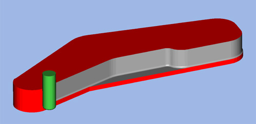
Roughing from Stock Model
3D Wizard roughing method is now able to generate toolpath based on a stock surface model. This greatly reduces the number of tool moves as compared to boundary definition using 2D curves. The stock model can be represented by single or multiple surfaces selected as check surfaces which should enclose the machined part. Any open edge of the stock is closed by extending the boundary profile to the lowest Z level of the stock. Roughing passes are created up to the lowest Z- level of the stock model.

Stock Model Creation
To improve stock model creation and handling several new functions are included in this latest release. The color “white” has been choosen as the standard color to be used for stock surface/model display. All white surfaces are now automatically displayed in transparent mode so that the machined part model inside remains visible. Also the stock model creation itself has been improved. The new command Create Stock in theSimulation & Stock Setup dialog creates the stock model based on several options.Rectangular & Cylindirical Block types can be defined using the corresponding parameters of the same dialog. Custom Stock type uses previously defined closed 2D curve selected as “current” curve and Z data parameters.
 Stockmodel surface display |
 Stockmodel used for 3D simulation |
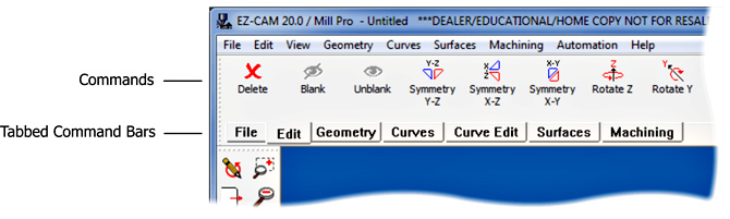
Command Manager (Tabbed Toolbars)
A new feature allows the user to organize groups of commands as multiple tabs at the top of the EZCAM application window. The number of tabs and their contents are fully customizable and the current tab can also be selected via its keyboard shortcut. This allows easeir access to any command button applicable to the current task.
Shortcut Toolbars
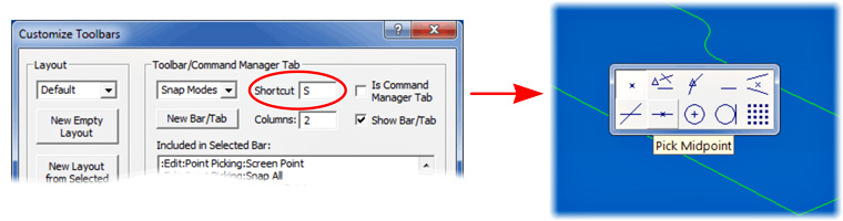
Any regular toolbar (not selected as command manager tab) can be displayed via its shortcut key at the current cursor location. User would normally need to move the cursor away from the part to select a specific command button from the toolbars around the drawing area, using the new feature the desired bar can be displayed right at the cursor tip ready for quick selection. EZCAM now allows the same button to be included in multiple bars. This allows the user to combine freqently used commands of different types (geometry, curves, snap modes, etc.) in his own shortcut toolbars for quick and easy acess whenever needed.
Screen Layout Management
In addition to all the previously mentioned toolbar enhancements, EZCAM now offers a new feature to create and select from multiple screen layouts which are saved in the initialization file EZ-CAM20.INI located in the application folder (EZCAMW/EZCAM20/). Transferring layouts between different computers can be accomplished by simply copying EZ-CAM20.INI file. Upon restarting EZCAM on the new system user can select the desired layout from the list in the Customize Toolbars dialog.

Enhanced Lollipop Tool Support
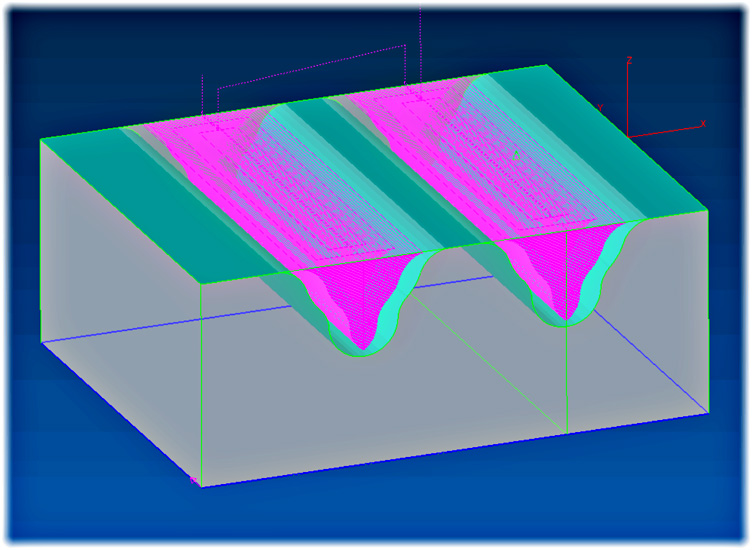
The definition of Lollipop tool has been extended by adding a new parameter for theArm diameter. Equidistant and Constant-Z finishing methods of the 3D wizard have been updated to support machining of undercut regions as far as possible by using such tools.
 Equidistant finishing – Lollipop tool |
 XZ view of toolpath showing undercut regions |
Z Rapid Move Optimization for Roughing
When roughing complex part shapes the machined area very often includes independent cavities. EZ-Mill’s roughing toolpath has been optimized to ensure that each cavity is machined to final depth before moving to the next one. In addition the number of rapid retracts between consecutive Z-levels inside have been reduced. If possible the tool will try to stay at Z-Clear distance above the last machined level when moving to the next plunge location. This greatly reduces unnecessary Z rapid moves between the roughing passes.
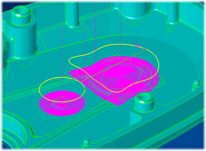
Equidistant Finishing multi Region Support
The equidistant finishing method has been enhanced to support the use of nested boundaries defining multiple independent regions to be finished. This can be achieved by chaining the desired profiles into one single curve and then selecting it as path for the equidistant finishing workstep. The new feature makes it much easier to re-finish certain areas of the part using different tools or strategies.
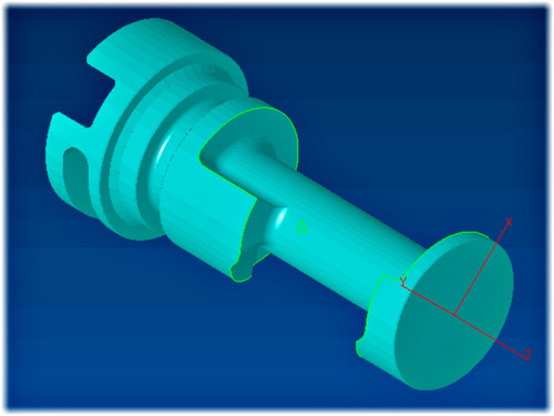
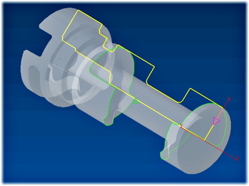
New Standard Silhouette Curve Command
A new standard Silhouette boundary curve option, previously only available in EZ-MILL Pro, has now been added to the other EZ-MILL, EZ-TURN and EZ-EDM modules. While the optional Pro version of Silhouette Curve command is still recommended when working with large and complex 3D models the newly introduced Standard Silhouette fulfills requirements of most cases. It creates a 2-D silhouette curve from selected surfaces that form a closed body. Curve loops are created for the outer boundary and any inner voids at Z0 in the XY plane (or XZ in TURN) of the active coordinate system. In EZ-TURN this function creates a curve that represents ½ of the spun profile ready to be converted into geometry for subsequent machining curve creation.
 Imported Solid Model in EZ-MILL Imported Solid Model in EZ-MILL |
 Silhouette Curve Silhouette Curve |
 Imported Solid Model in EZ-TURN Imported Solid Model in EZ-TURN |
 Silhouette Curve Silhouette Curve |
UCS On Surface Creation
The existing UCS on Geometry command, located in the View menu, has been updated to allow selection of a surface for new coordinate system definition. When a surface is selected the system aligns the current coordinate system (World or UCS) along the surface normal vector and in case of UCS definition its origin is set same as the WORLD origin. The distance between the origin of the currently active coordinate system and the selected surface is automatically copied into theWindows-Clipboard so that it can be pasted into the Z-Surf setting in the tool info dialog.
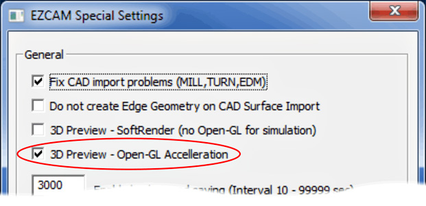
Increased 3D Simulation Performance
The speed of the solid simulation can now be increased by utilizing the Open-GLVertex-Buffer-Object option. The corresponding setting Open-GL Accelerationcan be activated using the Special INI Settings dialog available in the Help menu.
EDM » New Auto Start/End Command
The new Auto Start/End command located in the Curve menu of EZ-EDM automatically creates linear lead-in/out moves for all the closed profiles of the current curve based on the input lead length. Positive value input for length lets the system locate start/end points inside of the closed profiles (die) and negative values outside of the profiles (punch). The longest linear move is selected as the first element and in case of punch profiles system ensures that none of the computed start/end points are inside of any of the profiles. This new feature saves time especially when working with curves created by using the Face Boundary or XY Intersection commands with many loops but no start/end points defined.