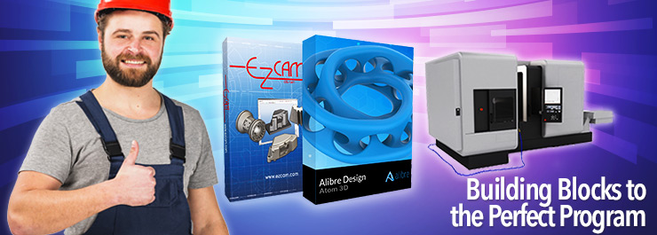
Get Solid With EZ-CAM
EZ-CAM and Alibre are a unique combination where machining and design come together. Alibre provides our EZ-CAM users with an interactive CAD package. Files from Alibre transfer instantly into EZ-CAM, and when there is a design change, you can sync your work to update your programming. The origin previously established in EZ-CAM remains intact during the transfer; therefore, your solid model maintains the correct orientation for machining.
EZ-CAM and Alibre complement each other, but EZ-CAM can work independently. Either way, solid models save EZ-CAM users time and the hassle of machining features by referencing blueprints. To access solid models from outside sources, EZ-CAM, and Alibre both import CAD files from other systems; this allows your customers to exchange a wider variety of file types with you. For more information on available file extensions, check out “Import Types” mentioned later in this article.
Increase Your Speed: All EZ-CAM products make use of curve boundaries for machining. Curves serve many purposes, such as paths for the tool to follow, a way to contain machining, or used to avoid certain regions. You can also generate curves to create surfaces. An example is the ability to cap holes. Curve boundaries can be created automatically by selecting faces using the following methods:
· Face Curve Boundary
· Silhouette Curve Boundary
· Intersection Curve Boundary
All of these options create closed curves, but you can manipulate them to form an open or modified profile. You can remove a section of a curve boundary in just two mouse clicks. If the curve you modified belongs to a work step, the machining updates automatically to the new path.
You can generate curve boundaries at once by using our Feature Recognition (detects bosses, pockets, contours, and face milling), and Hole Recognition (detects Z start height, hole depth, and hole diameter) found in our advanced milling products. And in EZ-EDM, automatically create XYUV work steps from top and bottom intersection curves.
Curves are not always necessary when creating work steps. You can add faces to work steps where their edges are assumed to be the machining boundaries. We use a point-and-click approach to machine 3D parts completely.
Checking For Accuracy: To fully understand if your part is complete and correct, we compare your tool path to the solid model using two methods: part-compare and Uncut Percentage.
Part-compare: With part-compare, known to EZ-CAM users as Create Uncut Solids, you can verify machining completeness and accuracy. You will find this feature in EZ-CAM’s stock setup, and when checked, you are notified of three things: (1) remaining stock [red], (2) gouging, or undercut [yellow], and (3) finished regions [green].
Uncut Percentage: Choosing Uncut Percentage will not only inform you of the percentage of how much material remains, but EZ-CAM also highlights those areas untouched by an oversized tool. Curve boundaries can be useful in containing additional machining in those regions.
Import Types:
EZ-CAM Turn Express & Mill Express
.iges, .dxf, .dwg, .step, .stp, .sat, and .eps
EZ-Mill, EZ-Mill PRO, EZ-EDM & EZ-Turn
.iges, .dxf, .dwg, STEP AP203/214 .step, .stp, Acis Solid Models .sat, Parasolid .x_t, .x_b, .xmt_bin, .xmt_txt, Rhino .3dm, SolidWorks .sldprt, .sldasm, STL Files .stl, VDAFS .vda, EPS
Alibre Atom3D
Step files (*.stp, *.step, *.stpz), SAT (*.sat), Autocad (dwg, dxf), SolidWorks (*.sldprt, *.sldasm).
Alibre Design–Includes Atom3D Imports
IGES (*.igs), Stat files (*.sat), Rhino (*.3dm), Image files (*.bmp, *.dib, *.rle, *.gif, *.tif, *.tiff, *.png, *.jpg, *.jpeg, *.jpe, *.jfif, *.emf, *.wmf), Parasolid (*.x_b, *.x_t, *.xmt_txt),
Alibre Expert–Includes Atom3D & Design Imports
Inventor (ipt, iam), ProE (*.prt, *.asm, *.xpr, *.xas), Catia (*.CATPart, *.CATProduct), SolidEdge (*.par, *.psm, *.asm), NX files (*.prt)


