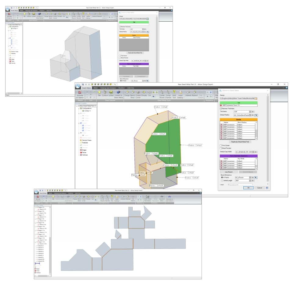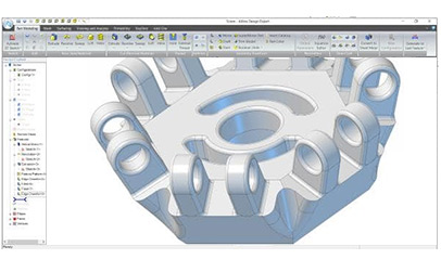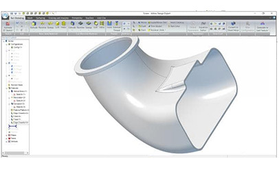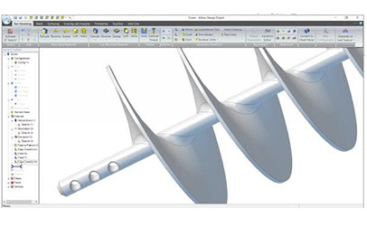
3D modeling for mechanical systems is the core competency of Alibre Design. Create complex parts from scratch or by using existing or imported parts as a reference. Assemble them together to create a final product, and evaluate the physical and motion characteristics.
3D Modeling for Mechanical Design
Learning at your fingertips
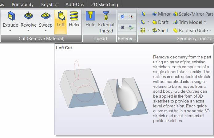
Find easy access to information about the tools in Alibre Design by hovering over any icon.
Fully parametric design
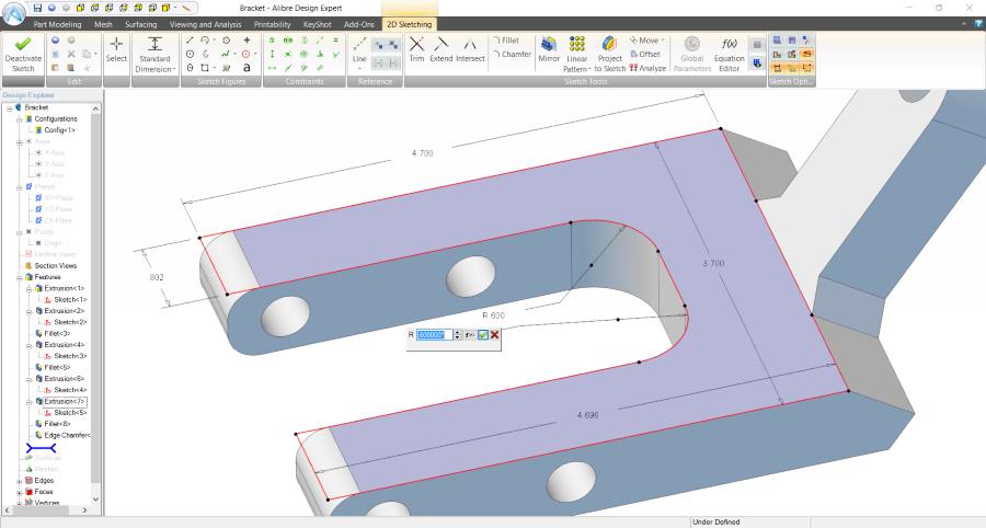
Everything in Alibre Design is parametric – driven by dimensions you specify. Beyond precision, a huge advantage of parametric modeling is that you can easily change the design by modifying the dimensions. You can also use the built-in Equation Editor to set up complex relationships, or import data from Excel to drive the design.
Infinite complexity, easily
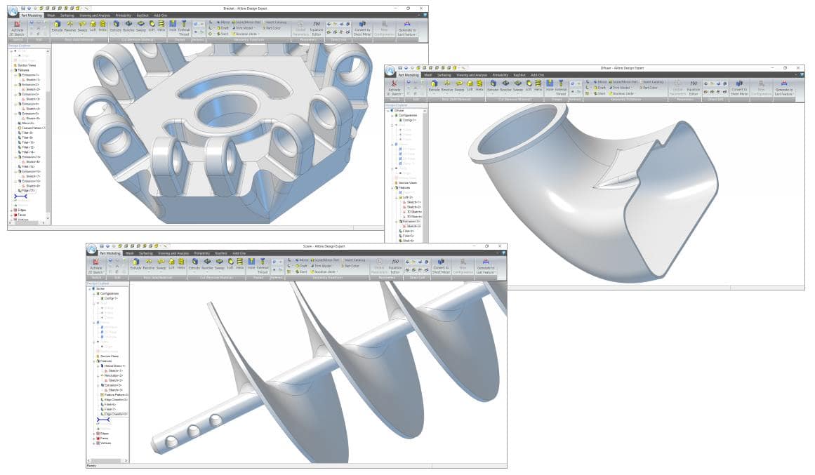
Create parts of any complexity with advanced modeling tools. The features in Alibre Design are geared for the design of mechanical systems. Lofted parts allow you to achieve more organic shapes and transitions.
3D Assembly Design
Drag and drop assembly creation
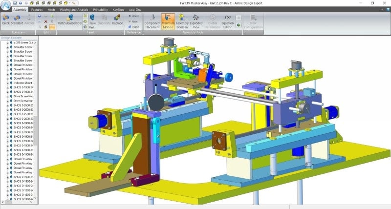
To put parts together into a mechanical system, simply drag parts onto other parts using intelligent snapping. The correct constraints are automatically applied, and you can modify them on the fly. When you’re done, the assembly will move like it would in the real world.
Exploded Views
Create exploded views using the auto-explode tool or by manually exploding your assembly. Publish exploded views into a 2D drawing, or into an animated 3D PDF so others can walk through assembly or disassembly step by step.
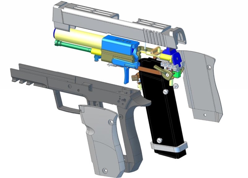
In-context part creation and editing
From within an assembly, you can create new parts or edit existing ones using other parts as a reference. Using a technique known as top-down design can speed up the design process by creating parts in the context of an existing assembly.
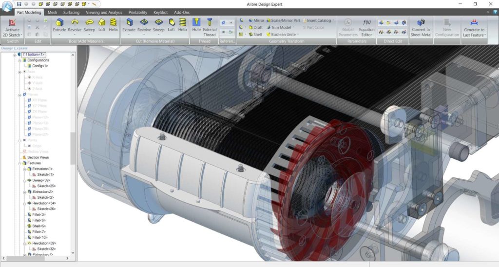
Create complex assemblies
Alibre Design can handle large and complex mechanical systems with many hundreds of parts. However, it is not intended for assemblies with thousands of parts.
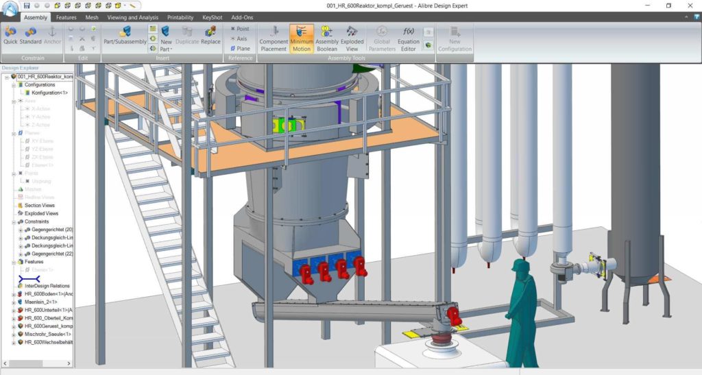
Analyze your design
Using tools like Interference Detection, you can quickly find problems and fix them before the first prototype. You can also find the combined physical characteristics of your model, such as its weight.
| Alibre Design Professional | Alibre Design Expert |
|
|---|---|---|
| Operating System Support | ||
| Windows 7 and later – 64 bit only | ||
| Learning | ||
| Integrated Tutorials | ||
| Easy, streamlined user interface | ||
| Basic Engraving | ||
| 3D Modeling | ||
| Accurate Physical Properties | ||
| 3D Part Modeling | ||
| 3D Assembly Creation | ||
| Drag-and-drop Constraint Management | ||
| Excel Driven Designs | ||
| Accurate Assembly Motion | ||
| Interference Detection | ||
| Re-use 2D Files (DWG/DXF) as the basis for 3D parts | ||
| Standard Part Libraries | ||
| Direct Editing for push/pull modeling | ||
| Intelligent part class and assembly class design | ||
| Advanced Assembly Features (Assembly Cut, Sketch, and Hole) | ||
| Global Parameters | ||
| Sheet Metal Modeling | ||
| Sheet Metal Design and Conversion | ||
| Design Communication | ||
| Basic 3D PDF Publishing | ||
| 2D PDF and Advanced 3D PDF Publishing | ||
| PhotoRealistic Rendering | ||
| 2D Drawings | ||
| Basic 2D toolset | ||
| Full 2D detailing toolset | ||
| Automatic updating of 2D when design changes | ||
| Automatic and manual BOM creation | ||
| Automatic title blocks | ||
| Import/Export | ||
| Import | ||
| IGES, SAT, STEP | ||
| OBJ, STL, WRL | ||
| DWG, DXF | ||
| Image Files | ||
| SolidWorks | ||
| Inventor, ProE/CREO, Catia, Parasolid, SolidEdge | ||
| Export | ||
| IGES, STEP, SAT | ||
| STL | ||
| DXF, DWG | ||
| Image formats | ||
| SolidWorks, Parasolid | ||
| 3D PDF | ||
| Surfacing | ||
| Surface Manipulation Tools | ||
