



Ready to try EZ-MILL Pro?
Download the trial version and evaluate EZ-MILL Pro for your CNC milling workflow, toolpath creation, and programming speed.
EZ-TURN 2023 introduces New Tech for Solid Model Programming
Would you panic without a keyboard? Not if you are programming in EZ-CAM. 3D solid models are not only a true representation of your part, but their features allow EZ-CAM to extract and apply operations automatically. Turning, boring, drilling, grooving, and threading worksteps are added without effort from our programmers. EZ-CAM’s advanced technology requires no machining paths, nor do you need to specify tool parameters and cutting strategies.
At most, a mouse click on the model may be required; this leaves us to say there is a substantial increase in ease of use. Our customers are excited about this fantastic breakthrough–because it works!
Watch this video, and we’ll show you “Turn Programming Without a Keyboard:”
Material, Stock Boundaries, & Tool Templates
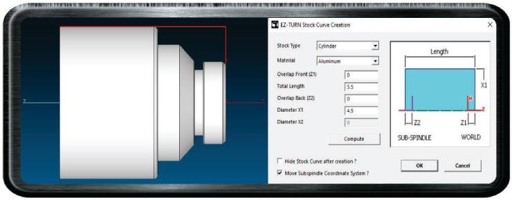
Figure 1 Stock is the First Step to Automation
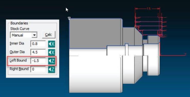
First, you will choose a material, then calculate your stock boundaries surrounding your solid model. The material determines which templates are loaded when you apply your operations—templates load tool information such as radius, tool number, maximum cut depth, etc.
Also loaded are your machining strategies. Depth of cut, constant surface speed, feed rates, and the like are all triggered by your tool selection.
EZ-CAM provides predetermined templates based on machining averages, but you can alter values on the fly for a one-time edit. Adding new tools and strategies is as easy as modifying fields and checkboxes, setting them as default, then changing the name.
Operations & Tool Selection
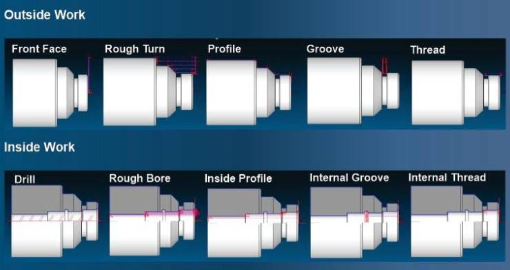
Figure 2 EZ-CAM Identifies a Solid Model’s Features
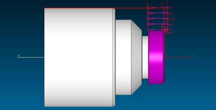
2-axis turning is a relatively basic concept with a limited number of operations. EZ-CAM takes advantage of this fact by searching the solid model for undercuts when using “Groove,” which includes face grooves; a through hole and shoulders when using “Drill,” where the depth is determined by how far the drill diameter can reach; rough material surrounding the O.D. or I.D when using “Turn” and “Bore,” where the tool path is created based on the boundaries set in the “3D Simulation Stock Curve;” and the overall part length for a finish “Profile,” where machining takes place along the O.D. or I.D. from one end to the other.
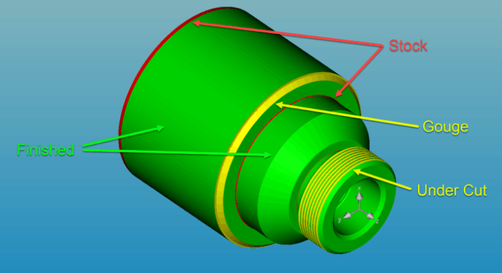
Part Compare
Part Compare is available in the simulation to ensure accuracy. You can use “Create Uncut Solids” in our “Stock Setup” to compare your work to the solid model. When you check this box, EZ-CAM displays any leftover stock, gouges, intended undercuts, and areas where the part has been machined to size.