The small dialog for selection of the current EZ-CAM module that came up in previous versions when the File/New command was selected has been replaced by a splash-screen dialog having many more options. When starting EZ-CAM or selecting the File/New command, the new dialog enables selection of the most recent part files for both MILL and TURN modes. In addition, when the desired file is not among these, one may alternatively click the Open… button to browse and find the file and open it. Either way the system will automatically start in the correct mode according to the selected file type. And, as with the old dialog, clicking any of the MILL-PRO, MILL or TURN buttons will start the system with an empty document in the mode selected.
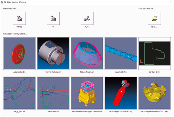
In addition to the new splash screen mentioned above, drag & drop files onto the EZ-CAM icon or the application window (an overlooked but very handy feature), has been reworked as well.
• Dropping any file onto the desktop icon opens the application in the correct mode depending on the file type (MILL or TURN)
• When dropping a file onto an existing EZ-CAM window, the file will be loaded on top of the already existing data. If the file type is different to the existing session, as for example dropping a TURN file onto a MILL session, an automatic restart in the new mode is done before loading the data.
• Any EZ-CAM supported CAD file (DXF, IGES, STEP, etc.) dropped onto the application window will automatically be imported.
When starting up new parts, users very often modify CAM generated NC code directly on the machine, due to part, tool, or machine-specific reasons. To keep the associated CAM file current, the machinist typically needs to note any changes and manually update the associated CAM file. Then, only after re-posting, will the code for this part include the changes.
Now, with EZ-CAM Web-Tools, we introduce a new method to revolutionize this process by enabling the user to remotely edit workstep-related parameters. With Web-Tools, part data (workstep parameter & snapshot image) can be uploaded to our new web service, EZ-CAM Online. The data can then be accessed via any web browser, running on any operating system (Android, iOS, Windows) on hardware such as tablets, smart phones, or laptops. Any modifications done via the remote devices can later be downloaded to EZ-CAM through Web-Tools to update the original part file on the PC.
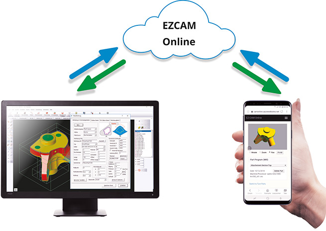
• Access to EZ-CAM Online service for registered users.
• EZ-CAM Online is supported in any browser on mobile devices using Android,
iOS, or Microsoft Mobile operating systems.
• Only workstep related machining information is shared, no sensitive part data (dimensions, geometry, surfaces, toolpaths, etc.) is uploaded.
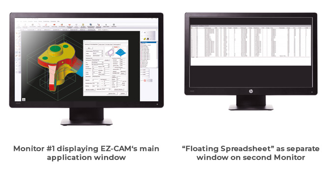
EZ-CAM’s unique Spreadsheet control » displaying the most important workstep related machining data for easier editing – can now be opened as a floating window to be moved around on the same machine’s screen or even on an external monitor. Such dual-monitor users will greatly benefit from keeping the separate spreadsheet window constantly open, allowing direct editing on one side while viewing the part and verifying the toolpath on the other.
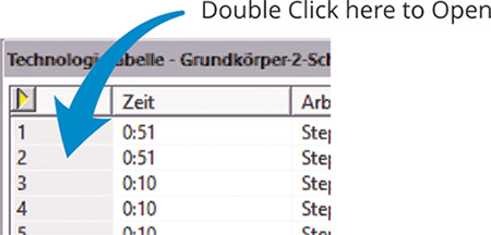
Although many key machining settings are directly accessible via the spreadsheet, sometimes users need to modify other settings and accordingly will open the full machining dialog. In previous versions this was not possible from inside the spreadsheet. Now in release 2019, the full machining dialog can be opened by a simple double-click in the first column of the spreadsheet in the row of the workstep to be edited.
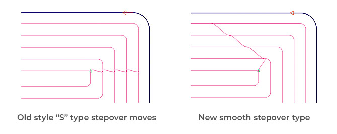
The standard contour parallel Pocketing cycle operation (HSM=OFF) is now using a new strategy to compute the toolpath, offering two big improvements over previous releases. First to name is the unlimited number of islands that can now be defined. The second and probably most important is the new smooth stepover type. In high feedrate environments, the old style “S” type often caused the machine to drastically reduce their cutting speed in order to perform the stepover. The new smooth type completely eliminates this drawback while also reducing tool wear. In addition, if the “Minimize Jumps” option is activated, the system tries to eliminate Z-rapid moves by moving to sub-regions at cutting depth if possible.
A new update to the 3D-Wizard’s Constant-Z Finishing method always includes passes for “flat regions”.
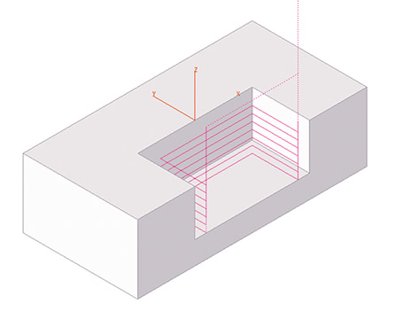
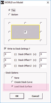
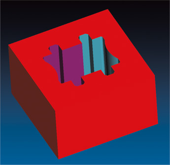
A new “Load Stock” option was added to the World on Model command, originally introduced in version 2018. This option loads any 3D file format with surfaces to be merged into one closed surface named stockSrf, representing the stock model with transparent color (white). In addition, the Stock Type on the Stock Setup dialog is automatically set to Custom stock.
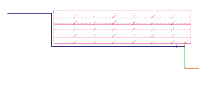
The Finishing Pass of the Zig-Zag cycle, intended to clean the ridges along the machined profile, now includes automatic lead-in moves to avoid over-stressing the tool when entering the remaining material. The lead-in length is automatically set to 50% of the defined Step Over distance.
The display performance of very large toolpaths has been updated and greatly improved.
The name of the last used post processor (machine specific NC code configuration file) is now directly saved into the part file together with the file extension used for the G-Code file. This information is then restored automatically when the partfile is opened again.
Create Worksheet Document now includes the image of the part at the top of the page.
The CAD import filters for STEP data has been modified and updated extensively. In addition, the AutoCAD DWG import has been upgraded to support latest 2018 file types.
Overlapping lines/arcs are deleted during CAD import so that chain command can now be used on the solid wireframe geometry as an alternative method for rapid curve creation.
Gradient is now the standard background color for the simulation window of all EZCAM modules.
The small dialog for selection of the current EZ-CAM module that came up in previous versions when the File/New command was selected has been replaced by a splash-screen dialog having many more options. When starting EZ-CAM or selecting the File/New command, the new dialog enables selection of the most recent part files for both MILL and TURN modes. In addition, when the desired file is not among these, one may alternatively click the Open… button to browse and find the file and open it. Either way the system will automatically start in the correct mode according to the selected file type. And, as with the old dialog, clicking any of the MILL-PRO, MILL or TURN buttons will start the system with an empty document in the mode selected.
In addition to the new splash screen mentioned above, drag & drop files onto the EZ-CAM icon or the application window (an overlooked but very handy feature), has been reworked as well.
• Dropping any file onto the desktop icon opens the application in the correct mode depending on the file type (MILL or TURN)
• When dropping a file onto an existing EZ-CAM window, the file will be loaded on top of the already existing data. If the file type is different to the existing session, as for example dropping a TURN file onto a MILL session, an automatic restart in the new mode is done before loading the data.
• Any EZ-CAM supported CAD file (DXF, IGES, STEP, etc.) dropped onto the application window will automatically be imported.
When starting up new parts, users very often modify CAM generated NC code directly on the machine, due to part, tool, or machine-specific reasons. To keep the associated CAM file current, the machinist typically needs to note any changes and manually update the associated CAM file. Then, only after re-posting, will the code for this part include the changes.
Now, with EZ-CAM Web-Tools, we introduce a new method to revolutionize this process by enabling the user to remotely edit workstep-related parameters. With Web-Tools, part data (workstep parameter & snapshot image) can be uploaded to our new web service, EZ-CAM Online. The data can then be accessed via any web browser, running on any operating system (Android, iOS, Windows) on hardware such as tablets, smart phones, or laptops. Any modifications done via the remote devices can later be downloaded to EZ-CAM through Web-Tools to update the original part file on the PC.
• Access to EZ-CAM Online service for registered users.
• EZ-CAM Online is supported in any browser on mobile devices using Android,
iOS, or Microsoft Mobile operating systems.
• Only workstep related machining information is shared, no sensitive part data (dimensions, geometry, surfaces, toolpaths, etc.) is uploaded.
EZ-CAM’s unique Spreadsheet control » displaying the most important workstep related machining data for easier editing – can now be opened as a floating window to be moved around on the same machine’s screen or even on an external monitor. Such dual-monitor users will greatly benefit from keeping the separate spreadsheet window constantly open, allowing direct editing on one side while viewing the part and verifying the toolpath on the other.
Although many key machining settings are directly accessible via the spreadsheet, sometimes users need to modify other settings and accordingly will open the full machining dialog. In previous versions this was not possible from inside the spreadsheet. Now in release 2019, the full machining dialog can be opened by a simple double-click in the first column of the spreadsheet in the row of the workstep to be edited.
The standard contour parallel Pocketing cycle operation (HSM=OFF) is now using a new strategy to compute the toolpath, offering two big improvements over previous releases. First to name is the unlimited number of islands that can now be defined. The second and probably most important is the new smooth stepover type. In high feedrate environments, the old style “S” type often caused the machine to drastically reduce their cutting speed in order to perform the stepover. The new smooth type completely eliminates this drawback while also reducing tool wear. In addition, if the “Minimize Jumps” option is activated, the system tries to eliminate Z-rapid moves by moving to sub-regions at cutting depth if possible.
A new update to the 3D-Wizard’s Constant-Z Finishing method always includes passes for “flat regions”.
A new “Load Stock” option was added to the World on Model command, originally introduced in version 2018. This option loads any 3D file format with surfaces to be merged into one closed surface named stockSrf, representing the stock model with transparent color (white). In addition, the Stock Type on the Stock Setup dialog is automatically set to Custom stock.
The Finishing Pass of the Zig-Zag cycle, intended to clean the ridges along the machined profile, now includes automatic lead-in moves to avoid over-stressing the tool when entering the remaining material. The lead-in length is automatically set to 50% of the defined Step Over distance.
The display performance of very large toolpaths has been updated and greatly improved.
The name of the last used post processor (machine specific NC code configuration file) is now directly saved into the part file together with the file extension used for the G-Code file. This information is then restored automatically when the partfile is opened again.
Create Worksheet Document now includes the image of the part at the top of the page.
The CAD import filters for STEP data has been modified and updated extensively. In addition, the AutoCAD DWG import has been upgraded to support latest 2018 file types.
Overlapping lines/arcs are deleted during CAD import so that chain command can now be used on the solid wireframe geometry as an alternative method for rapid curve creation.
Gradient is now the standard background color for the simulation window of all EZCAM modules.
The small dialog for selection of the current EZ-CAM module that came up in previous versions when the File/New command was selected has been replaced by a splash-screen dialog having many more options. When starting EZ-CAM or selecting the File/New command, the new dialog enables selection of the most recent part files for both MILL and TURN modes. In addition, when the desired file is not among these, one may alternatively click the Open… button to browse and find the file and open it. Either way the system will automatically start in the correct mode according to the selected file type. And, as with the old dialog, clicking any of the MILL-PRO, MILL or TURN buttons will start the system with an empty document in the mode selected.
In addition to the new splash screen mentioned above, drag & drop files onto the EZ-CAM icon or the application window (an overlooked but very handy feature), has been reworked as well.
• Dropping any file onto the desktop icon opens the application in the correct mode depending on the file type (MILL or TURN)
• When dropping a file onto an existing EZ-CAM window, the file will be loaded on top of the already existing data. If the file type is different to the existing session, as for example dropping a TURN file onto a MILL session, an automatic restart in the new mode is done before loading the data.
• Any EZ-CAM supported CAD file (DXF, IGES, STEP, etc.) dropped onto the application window will automatically be imported.
When starting up new parts, users very often modify CAM generated NC code directly on the machine, due to part, tool, or machine-specific reasons. To keep the associated CAM file current, the machinist typically needs to note any changes and manually update the associated CAM file. Then, only after re-posting, will the code for this part include the changes.
Now, with EZ-CAM Web-Tools, we introduce a new method to revolutionize this process by enabling the user to remotely edit workstep-related parameters. With Web-Tools, part data (workstep parameter & snapshot image) can be uploaded to our new web service, EZ-CAM Online. The data can then be accessed via any web browser, running on any operating system (Android, iOS, Windows) on hardware such as tablets, smart phones, or laptops. Any modifications done via the remote devices can later be downloaded to EZ-CAM through Web-Tools to update the original part file on the PC.
• Access to EZ-CAM Online service for registered users.
• EZ-CAM Online is supported in any browser on mobile devices using Android,
iOS, or Microsoft Mobile operating systems.
• Only workstep related machining information is shared, no sensitive part data (dimensions, geometry, surfaces, toolpaths, etc.) is uploaded.
EZ-CAM’s unique Spreadsheet control » displaying the most important workstep related machining data for easier editing – can now be opened as a floating window to be moved around on the same machine’s screen or even on an external monitor. Such dual-monitor users will greatly benefit from keeping the separate spreadsheet window constantly open, allowing direct editing on one side while viewing the part and verifying the toolpath on the other.
Although many key machining settings are directly accessible via the spreadsheet, sometimes users need to modify other settings and accordingly will open the full machining dialog. In previous versions this was not possible from inside the spreadsheet. Now in release 2019, the full machining dialog can be opened by a simple double-click in the first column of the spreadsheet in the row of the workstep to be edited.
The display performance of very large toolpaths has been updated and greatly improved.
EZ-TURN introduces the new Peck Step parameter for Turn, Bore and Face roughing cycles. Clearance distance between two pecking steps is 0.1 mm, and retract and engage moves are controlled by “Engage Angle”, “Clearance”, “Withdraw Angle” and “Withdraw Distance” parameters.
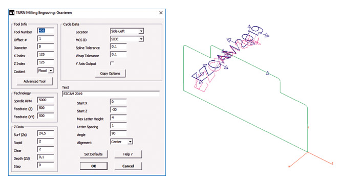
Improving on previous releases, the new Engraving cycle lets you define the technology data, as well as the engraving specific parameters, all in one dialog. The path curve is created automatically, and toolpath can be verified right away, anytime. Modifying the text only requires opening the workstep, changing the text, closing the dialog and then re-verifying or posting the toolpath.
The Cutoff cycle has gotten a major upgrade with the addition of some very frequently requested features:
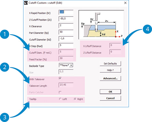
 The new settings “Cutoff Diameter (F-reduced)” and “Feed Factor” allow performing the final stage of the cutoff process using a reduced feedrate.
 As an alternative to the (newly updated) Parts Catcher option, the user can also define a “Takeover Length” that is passed to the NC code that handles part-takeover on Sub-Spindle machines.
 Regular EZ-CAM cycles always explicitly use the left edge of a cutoff tool » the new “Tooltip” option of the “Cutoff” cycle, however, allow you to select which edge of the tool, left or right, is measured and defined by the corresponding offset on the machine. For this the cycle will use the workstep’s “Tool Width” setting to correctly calculate toolpath and NC code, respectively.
 “X Liftoff Distance” = X retract distance when doing multiple X steps during the cutoff.
“Z Liftoff Distance” = Z retract distance after cutoff move.
The name of the last used post processor (machine specific NC code configuration file) is now directly saved into the part file together with the file extension used for the G-Code file. This information is then restored automatically when the partfile is opened again.
Create Worksheet Document now includes the image of the part at the top of the page.
The CAD import filters for STEP data has been modified and updated extensively. In addition, the AutoCAD DWG import has been upgraded to support latest 2018 file types.
Overlapping lines/arcs are deleted during CAD import so that chain command can now be used on the solid wireframe geometry as an alternative method for rapid curve creation.
Gradient is now the standard background color for the simulation window of all EZCAM modules.
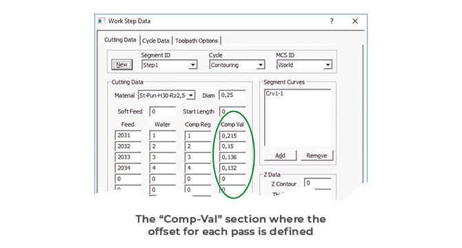
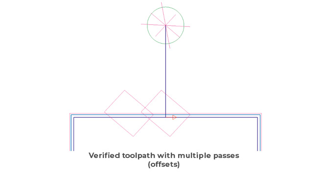
The Contouring, XYUV and Die/Punch cycles now verify the wirepath using different offset values for multiple passes. If the technology table provides valid offset values (between 0 and twice the wire diameter), the system will use these, otherwise it will compute a standard value between the wire radius and wire diameter for each pass. In the case of multiple passes, the interval will be divided equally among those.
The updated 3D simulation now uses different colors for each pass along a certain profile and hides the bodies split away from the stock automatically. In addition, the background color of the simulation window has been changed to a gradient display.
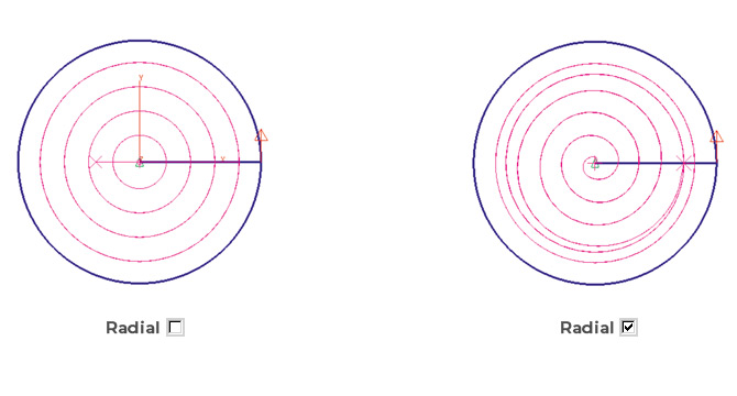
In release 2018, the Pocketing cycle’s wirepath was converted to the more efficient trochoidal style. In the 2019 release the new Radial setting gives the option to switch between old-style parallel pocketing (Radial=Off) and the new trochoidal style (Radial=On). In addition, the trochoidal style has seen several improvements in respect to reduced cut/thread occurrences and better wire/part collision checks while moving inside the pocket at rapid feedrates.
The CAD import filters for STEP data has been modified and updated extensively. In addition, the AutoCAD DWG import has been upgraded to support latest 2018 file types.
Overlapping lines/arcs are deleted during CAD import so that chain command can now be used on the solid wireframe geometry as an alternative method for rapid curve creation.
Gradient is now the standard background color for the simulation window of all EZCAM modules.
The small dialog for selection of the current EZ-CAM module that came up in previous versions when the File/New command was selected has been replaced by a splash-screen dialog having many more options. When starting EZ-CAM or selecting the File/New command, the new dialog enables selection of the most recent part files for both MILL and TURN modes. In addition, when the desired file is not among these, one may alternatively click the Open… button to browse and find the file and open it. Either way the system will automatically start in the correct mode according to the selected file type. And, as with the old dialog, clicking any of the MILL-PRO, MILL or TURN buttons will start the system with an empty document in the mode selected.
In addition to the new splash screen mentioned above, drag & drop files onto the EZ-CAM icon or the application window (an overlooked but very handy feature), has been reworked as well.
• Dropping any file onto the desktop icon opens the application in the correct mode depending on the file type (MILL or TURN)
• When dropping a file onto an existing EZ-CAM window, the file will be loaded on top of the already existing data. If the file type is different to the existing session, as for example dropping a TURN file onto a MILL session, an automatic restart in the new mode is done before loading the data.
• Any EZ-CAM supported CAD file (DXF, IGES, STEP, etc.) dropped onto the application window will automatically be imported.
When starting up new parts, users very often modify CAM generated NC code directly on the machine, due to part, tool, or machine-specific reasons. To keep the associated CAM file current, the machinist typically needs to note any changes and manually update the associated CAM file. Then, only after re-posting, will the code for this part include the changes.
Now, with EZ-CAM Web-Tools, we introduce a new method to revolutionize this process by enabling the user to remotely edit workstep-related parameters. With Web-Tools, part data (workstep parameter & snapshot image) can be uploaded to our new web service, EZ-CAM Online. The data can then be accessed via any web browser, running on any operating system (Android, iOS, Windows) on hardware such as tablets, smart phones, or laptops. Any modifications done via the remote devices can later be downloaded to EZ-CAM through Web-Tools to update the original part file on the PC.
• Access to EZ-CAM Online service for registered users.
• EZ-CAM Online is supported in any browser on mobile devices using Android,
iOS, or Microsoft Mobile operating systems.
• Only workstep related machining information is shared, no sensitive part data (dimensions, geometry, surfaces, toolpaths, etc.) is uploaded.
EZ-CAM’s unique Spreadsheet control » displaying the most important workstep related machining data for easier editing – can now be opened as a floating window to be moved around on the same machine’s screen or even on an external monitor. Such dual-monitor users will greatly benefit from keeping the separate spreadsheet window constantly open, allowing direct editing on one side while viewing the part and verifying the toolpath on the other.
Although many key machining settings are directly accessible via the spreadsheet, sometimes users need to modify other settings and accordingly will open the full machining dialog. In previous versions this was not possible from inside the spreadsheet. Now in release 2019, the full machining dialog can be opened by a simple double-click in the first column of the spreadsheet in the row of the workstep to be edited.
The standard contour parallel Pocketing cycle operation (HSM=OFF) is now using a new strategy to compute the toolpath, offering two big improvements over previous releases. First to name is the unlimited number of islands that can now be defined. The second and probably most important is the new smooth stepover type. In high feedrate environments, the old style “S” type often caused the machine to drastically reduce their cutting speed in order to perform the stepover. The new smooth type completely eliminates this drawback while also reducing tool wear. In addition, if the “Minimize Jumps” option is activated, the system tries to eliminate Z-rapid moves by moving to sub-regions at cutting depth if possible.
A new update to the 3D-Wizard’s Constant-Z Finishing method always includes passes for “flat regions”.
A new “Load Stock” option was added to the World on Model command, originally introduced in version 2018. This option loads any 3D file format with surfaces to be merged into one closed surface named stockSrf, representing the stock model with transparent color (white). In addition, the Stock Type on the Stock Setup dialog is automatically set to Custom stock.
The Finishing Pass of the Zig-Zag cycle, intended to clean the ridges along the machined profile, now includes automatic lead-in moves to avoid over-stressing the tool when entering the remaining material. The lead-in length is automatically set to 50% of the defined Step Over distance.
The display performance of very large toolpaths has been updated and greatly improved.
EZ-TURN introduces the new Peck Step parameter for Turn, Bore and Face roughing cycles. Clearance distance between two pecking steps is 0.1 mm, and retract and engage moves are controlled by “Engage Angle”, “Clearance”, “Withdraw Angle” and “Withdraw Distance” parameters.
Improving on previous releases, the new Engraving cycle lets you define the technology data, as well as the engraving specific parameters, all in one dialog. The path curve is created automatically, and toolpath can be verified right away, anytime. Modifying the text only requires opening the workstep, changing the text, closing the dialog and then re-verifying or posting the toolpath.
The Cutoff cycle has gotten a major upgrade with the addition of some very frequently requested features:
The new settings “Cutoff Diameter (F-reduced)” and “Feed Factor” allow performing the final stage of the cutoff process using a reduced feedrate.
As an alternative to the (newly updated) Parts Catcher option, the user can also define a “Takeover Length” that is passed to the NC code that handles part-takeover on Sub-Spindle machines.
Regular EZ-CAM cycles always explicitly use the left edge of a cutoff tool » the new “Tooltip” option of the “Cutoff” cycle, however, allow you to select which edge of the tool, left or right, is measured and defined by the corresponding offset on the machine. For this the cycle will use the workstep’s “Tool Width” setting to correctly calculate toolpath and NC code, respectively.
“X Liftoff Distance” = X retract distance when doing multiple X steps during the cutoff.
“Z Liftoff Distance” = Z retract distance after cutoff move.
The Contouring, XYUV and Die/Punch cycles now verify the wirepath using different offset values for multiple passes. If the technology table provides valid offset values (between 0 and twice the wire diameter), the system will use these, otherwise it will compute a standard value between the wire radius and wire diameter for each pass. In the case of multiple passes, the interval will be divided equally among those.
The updated 3D simulation now uses different colors for each pass along a certain profile and hides the bodies split away from the stock automatically. In addition, the background color of the simulation window has been changed to a gradient display.
In release 2018, the Pocketing cycle’s wirepath was converted to the more efficient trochoidal style. In the 2019 release the new Radial setting gives the option to switch between old-style parallel pocketing (Radial=Off) and the new trochoidal style (Radial=On). In addition, the trochoidal style has seen several improvements in respect to reduced cut/thread occurrences and better wire/part collision checks while moving inside the pocket at rapid feedrates.
The name of the last used post processor (machine specific NC code configuration file) is now directly saved into the part file together with the file extension used for the G-Code file. This information is then restored automatically when the partfile is opened again.
Create Worksheet Document now includes the image of the part at the top of the page.
The CAD import filters for STEP data has been modified and updated extensively. In addition, the AutoCAD DWG import has been upgraded to support latest 2018 file types.
Overlapping lines/arcs are deleted during CAD import so that chain command can now be used on the solid wireframe geometry as an alternative method for rapid curve creation.
Gradient is now the standard background color for the simulation window of all EZCAM modules.