


MILL Express / MILL / MILL-Pro » UltraHSM Pocketing
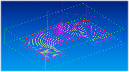
New cutting tools and latest developments in CNC technologies let us redesign the toolpath strategy of EZCAM’s pocketing cycle. Circular cutting passes in combination with radial ramp in/out moves guarantee a continuous toolpath without any sharp corners. As another important feature of this method, angle of contact for the cutting tool remains much smaller than the maximum value of 180 deg. Very high cutting speeds can be sustained using step-over values of 0.1 – 0.5 x D (D=Tool Diameter). Whereas with traditional methods Z-Step cannot exceed 0.5 x D this new strategy allows a cutting depth of 2 x D.
Benefits:
- Machining time can be reduced by up to 50%.
- Small angle of contact increases tool life by up to 10 times.
- Continuous toolpath without any sharp corners.
- Constant material removal rate is obtained by feedrate optimization.
- Rapid cross over and plunge moves are minimized.
- Older machines without high-speed capability benefit from increased tool life.
In addition to above listed benefits, there are more technical details and features, which can be used to fine-tune some aspects of this new toolpath strategy.
Start Point – First plunge point is computed automatically by the cycle. It is also possible to let the tool-path start from a given point by appending it to the pocket curve via rapid link. The usual plunge options (Helical, etc.) can still be activated.
Connection between cutting passes – Individual cutting passes are connected via fast-linear moves at 0.005in above the current cutting depth using the maximum feedrate setting of the selected postprocessor. Rise and decent between this higher z-level and cutting passes are performed via helical ramp in/out moves at pocket boundary.
Finish Path – Rest material left by the roughing passes along the pocket boundaries can be cleaned up using the finish path option. Without the final finish path we guarantee that the rest material along the boundaries is less than the step over value.
Face Milling – In previous versions of EZCAM, face-milling option has been available for the Zig-Zag cycle only. Now pocketing cycle, with HSM option activated, offers face milling as well. The corresponding toolpath extends towards outside of the pocket curve by the value of tool diameter plus the input finish allowance amount.
Constant Material Removal Rate – When First Feed parameter is left as zero, feedrate optimization is performed for the entire toolpath to guarantee constant material removal rate for all moves. If another value is input for the first feed parameter then all ramp in-out moves are output with this feedrate whereas Feed-XY is assigned to all cutting passes.
Open Edges – If some moves of the pocket boundary are designated as open edge using the Motion Manager start point (seed point) of the roughing toolpath is located in the middle of the corresponding curve element.
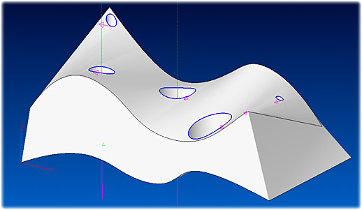
MILL / MILL-Pro » Drilling with 3D Curves
Whereas until now drilling cycles support only 2D Curves the latest version of EZCAM allows selection of holes defined as 3D curves. Such curves are usually created directly from the Surface/Solid model using the Face Boundary command. Tool axis is kept parallel to the z-axis of the selected machine coordinate system (MCS).
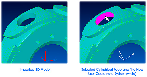
MILL / MILL-Pro / Turn » UCS Creation at 3D Holes
When part programming for holes in 3D models it is often required to define coordinate systems aligned along the axes of these holes. Such coordinate systems could not be easily created especially if the top or bottom end of the hole is not planar. Therefore the command UCS on Geometry has been modified to create a UCS with its z-axis parallel to the axis of the cylindrical face selected using the surface discrimination option. The origin of the UCS is the World origin.
MILL / TURN / EDM » Delete Multiple Curve Moves
The new command “Delete From/To” allows deletion of multiple curve moves at once. It prompts to select 2 elements and removes all moves from the start point of first selected element to the last point of second selected element from the curve.
MILL / TURN / EDM » 3D Curve Offset
The “Curve Offset” command has been enhanced. If the curve is 3D and a non-zero offset value is input this command now performs a 3D offset operation similar to the contouring cycle with projection=3D. If 3D offset is not preferred the curve should be first projected onto the XY plane by inputting zero as the offset value and then the required 2D offset is input.
MILL / TURN / EDM » Updated Toolbar Customization and Display
EZCAM toolbars and Command Manager (first introduced in EZCAM version 20), have been updated to follow the latest Microsoft Office style and functionality.
The currently selected command is now highlighted in light blue and the selected tab in white for easier orientation, and commands can now be grouped into Popup menus.
Right-clicking on a command will open the Toolbar Editing menu with four options:
- Select Delete to remove the selected command from its toolbar.
- Select Start Group to insert a separator into the toolbar immediately before the command.
- Select New Popup to insert a new Popup menu in place of the selected command in the toolbar and insert the selected command into the new Popup menu.
- Select Customize to open the Customize dialog and switch the application into Editing Mode.
- Editing Mode enables In-place Editing, via drag-and-drop, so that you may move a command by dragging it to a new location in the same or a different toolbar or Popup menu. Drag a command from its toolbar or Popup menu into the drawing window to simply remove it.
Alternatively, you can put the application into Editing Mode by holding down the ALT key.
The Customize dialog (also openable from the View menu, as in previous EZCAM versions) has been updated to add support for the Toolbar Editing menu options and for Popup menu editing. A layout may be locked to prevent accidental changes by checking the appropriate box in the dialog. On closing the EZCAM application, current layout settings are stored in the current user’s registry section of the Windows operating system. In case users want to share identical layouts on multiple computers, the Customize dialog now has an option to export all registry settings to a file with the “.reg” extension. By copying that file to other computers and double-clicking on it, the exported settings can be imported into the computers’ registries.
All Modules » Updated CAD Data Translation
The IGES, SAT, Solidworks, Parasolid, STEP, VDAFS CAD data translators have been updated to improve translation quality. Solidworks 2014 .sldprt files can now be imported. These changes ensure complete compatibility with the latest versions of popular CAD systems.