Following a very positive reception for the ALIBRE CAD Add-In that we introduced in EZ-CAM V2020, we’ve further extended EZ-CAM’s CAD connectivity by creating a similar direct Add-In for the world-leading CAD System, SOLIDWORKS.
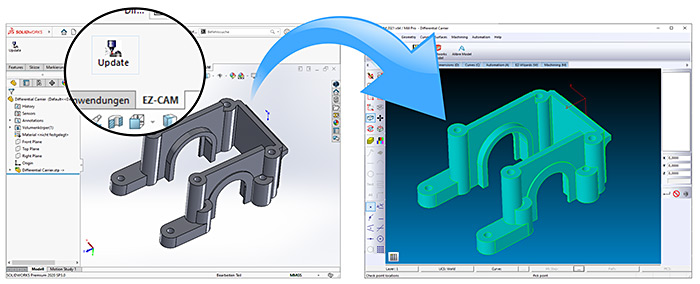
When single-clicked, the new plug-In command instantly transfers the model from the current SolidWorks session to the active EZ-CAM module. By hiding undesired bodies inside SolidWorks before a transfer, the user can limit the transfer to only the necessary parts of an assembly. The Add-In will be installed automatically if a local SolidWorks installation is detected during EZ-CAM v2021 installation.
EZ-CAM’s existing “Update SolidWorks” command has also been enhanced. It now automatically transfers each part of a SolidWorks assembly into a new EZ-CAM layer with ID=. And of course, EZ-CAM has been updated to also load SolidWorks v2020 files (*.SLDPRT) via its regular “File Open” command.
The existing EZ-CAM Alibre Add-on module has been further optimized for quick model update after every modification in the active Alibre session. The Add-on’s “Transfer” command instantly transfers each part in the assembly into a new EZ-CAM layer with ID=
. Further part selection in EZ-CAM is then easily handled via the “Layer Manager” introduced in EZ-CAM release v2020.
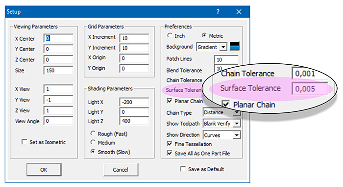
The new “Surface Tolerance” setting in the “View / Setup” dialog allows the user to specify the tessellation quality of the model imported from CAD files according to the one’s machining tolerance needs. This setting is also applied to models directly transferred from an Alibre and SolidWorks session using their respective EZ-CAM Add-In’s. By default this setting is set to 0.01 mm in metric, or 0.001 for inch mode.
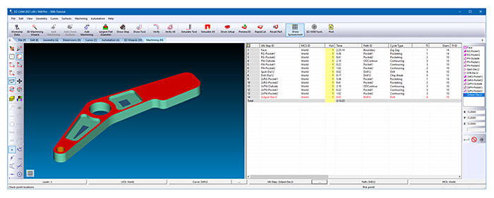
A new option “Dock Spreadsheet to Right” in the “View / Customize” dialog permits the “Spreadsheet” control to be docked to the right side of the screen. With this new feature, users can make better use of wider screens and keep the Spreadsheet always visible on the right side. Naturally, the Spreadsheet can still instead be made to float and moved to a second screen.
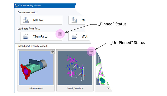
The “Pin-down” feature that has already been available in the startup window for recently loaded part files has been added now to the four “Folder” buttons there. This enables the user to fix the display of most frequently used folders so they will be readily available.
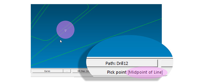
The “Snap-mode” used for the currently snapped location on the screen is displayed in the status bar’s right-side message area, e.g. “Pick point [Midpoint of Line]”. This new feature is especially helpful when the snap mode is set to one of the multi-type settings such as “Snap All”.
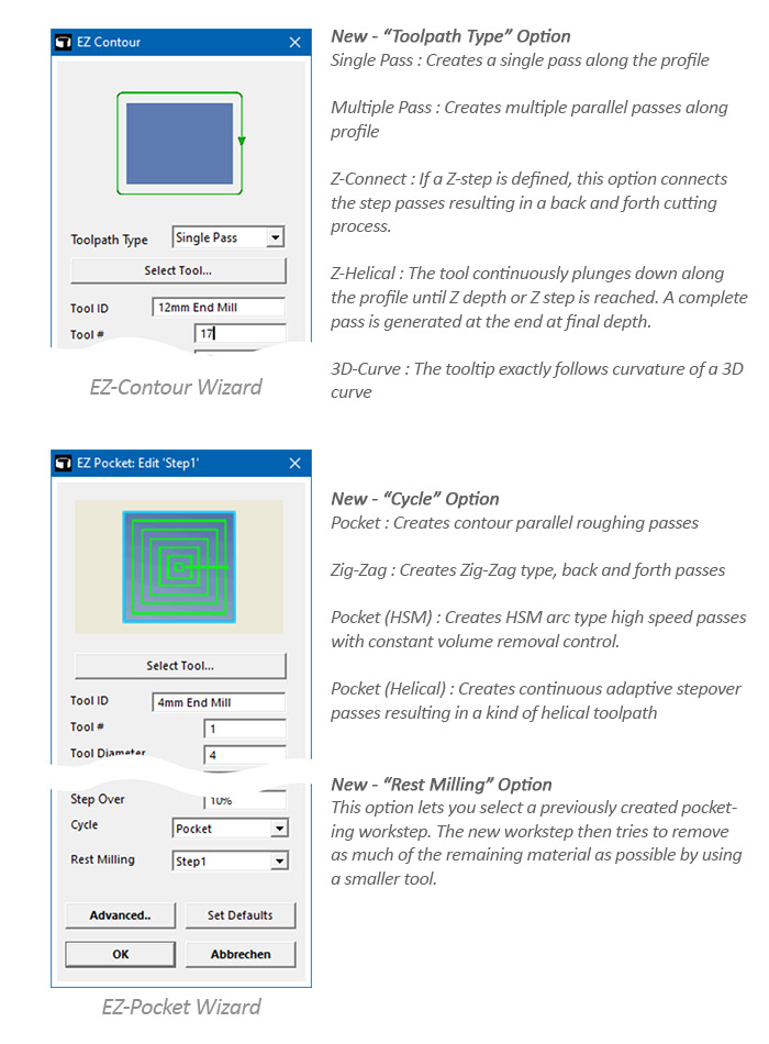
Worksteps created by the “Contour”, “Pocket” and “Face” wizards can now be edited using the same wizard dialogs. Of course, the full set of parameters and settings are always available via the “Advanced” button. The new “Select Tool” option provides access to EZCAM’s tool library, while additional toolpath and cycle options ease the usage of EZCAM’s various toolpath combinations.
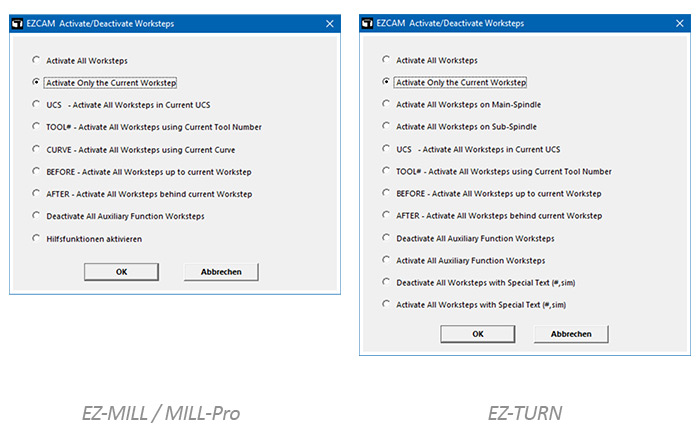
A new “Activate-Deactivate Worksteps” macro has been added to the “Help” menu “Toolbox” list. This macro allows single-click activation or deactivation of worksteps based on certain rules. For example: one can deactivate all worksteps below that one currently selected. This feature might be used when only certain worksteps need to be verified or simulated. In TURN mode one can also deactivate all sub-spindle worksteps for posting main-spindle work only. These are just some examples. Please note that such macros can also be assigned to certain function keys (F1-F12, via “EZCAM.INI” settings) for faster access.
It is now possible to apply any of the transformation commands (Translate, Move, Rotate, etc.) directly to the “WORLD” coordinate system. This offers another flexible method to set the main part origin. Alibre and Solidworks model update commands recognize the new origin set by this new method. (Please note that the “All” select command does not select the WORLD system, which can only be selected from the list box on the right side of the screen.)
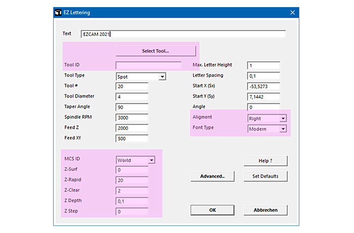
The “Lettering” cycle has been updated and enhanced with some new options. The new “Select Tool” button connects to EZ-CAM’s mill tool library for tool selection. Using the “Alignment” setting enables the user to align (Left, Right, Center) the text based on the defined X and Y start coordinates. The “Font” list offers two types of single-line fonts to create efficient NC-Code. Particularly noteworthy is the addition of the “Z-Data” settings, as this greatly reduces the frequency of needing to continue to the “Advanced” machining dialog tab for further editing.
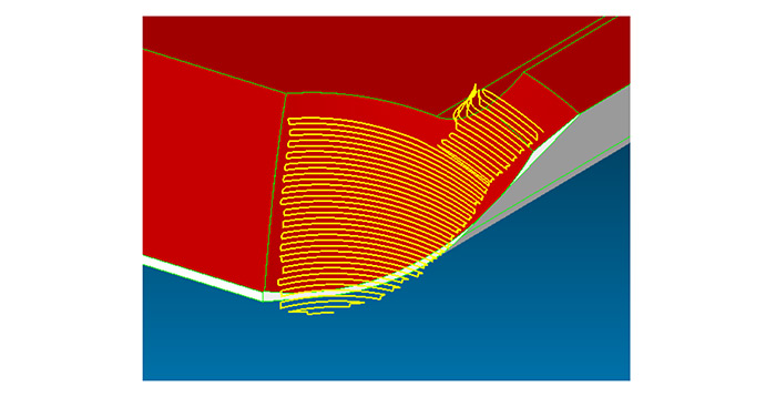
The “Open Surface” link type in 3D-Wizard’s “Constant-Z” finishing method has been renamed to “Zig-zag” and now can be successfully used for all tool types, including undercut tools, to shorten the machining time by eliminating rapid-over moves between consecutive z-cuts.
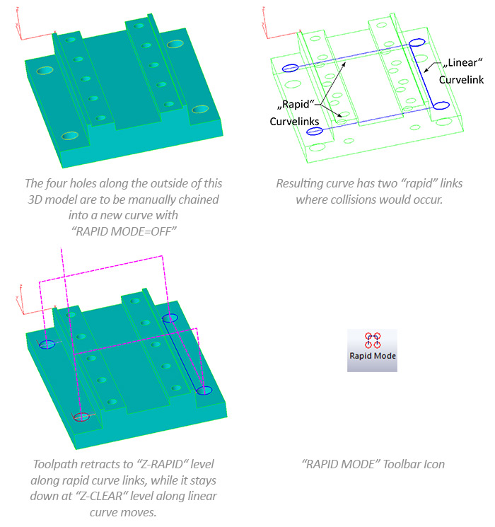
When manually chaining circle entities into curves, the system now checks if the connection at Z-Clear would cause collision with any of the visible surfaces. If the connection between two circles at “Z-Clear” default level would cause a collision, the circles are connected using a rapid curve link – otherwise the connection link will be of linear type. Such rapid curve links will cause the toolpath to retract to “Z-RAPID” level above the surface before continuing to the next hole to be drilled. Please note, that in order to make use of this new feature, the “Rapid Mode” curve command needs to be set to “Off” ( = Linear link if possible ). Otherwise all curve links will be of the type “Rapid” automatically.
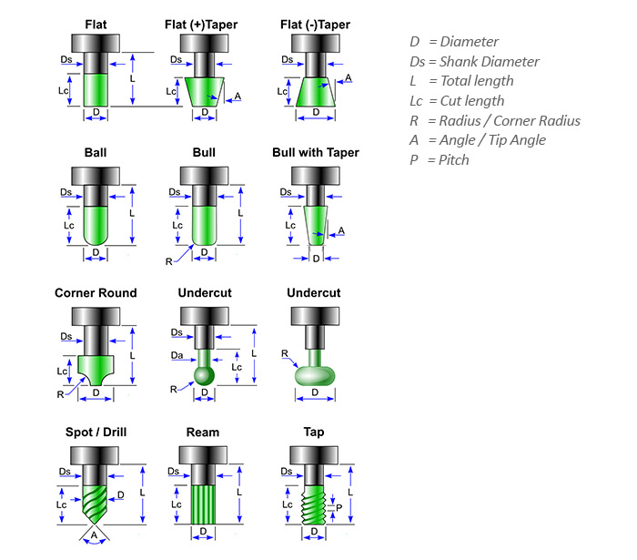
To optimize visual toolpath check in 3D Preview, new tool properties “Cut Length” and “Shank Diameter” have been added. These settings improve the tool display and allow better clash detection for standard and custom tools. Below see the new settings in combination with the various tool types:
The new “Return to Z-Clear” option in the Z-Data section of Work Step Data allows 2.5D contouring, pocketing and zig-zag toolpaths to rapid over at “Z-Clear” height when connecting consecutive Z level passes.
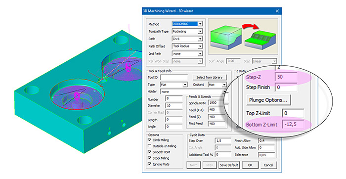
3D Wizard Constant-Z methods can now perform a single z-level cut defined by the lower z-limit if the z-step is set to a big enough value.
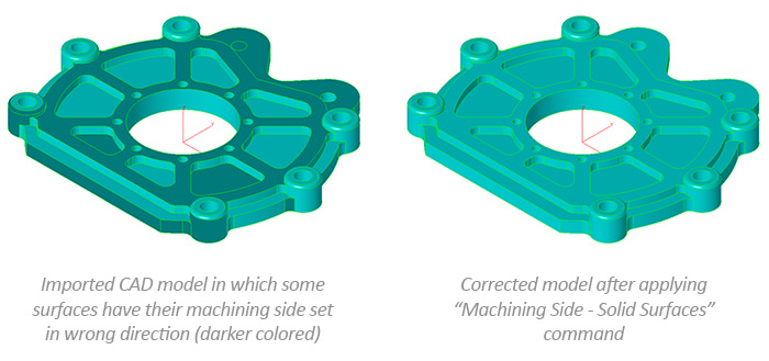
The “Machining Side – Solid Surfaces” command has been much improved in speed and accuracy. This command should be applied when the user observes faces of the closed body having the wrong side selected after a CAD import.
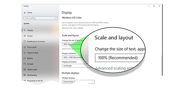
While older windows versions, including first Windows 10 builds, provided options to directly set the font and size used in the application dialogs, more recent Windows 10 builds only permit users to adapt the letter size to their screen size through a global scaling factor. This change required us to modify EZ-CAM’s user interface with the help of a major update for our “WinBasic” automation language engine. In the course of this rework, we have revised and improved many of the macro dialogs, adding new functions and buttons such as the new “Select Tool” command button in the MILL / MILL Express dialogs. We have successfully tested the rework with scale factors of up to 200%.
A new option “Dock Spreadsheet to Right” in the “View / Customize” dialog permits the “Spreadsheet” control to be docked to the right side of the screen. With this new feature, users can make better use of wider screens and keep the Spreadsheet always visible on the right side. Naturally, the Spreadsheet can still instead be made to float and moved to a second screen.
The “Pin-down” feature that has already been available in the startup window for recently loaded part files has been added now to the four “Folder” buttons there. This enables the user to fix the display of most frequently used folders so they will be readily available.
The “Snap-mode” used for the currently snapped location on the screen is displayed in the status bar’s right-side message area, e.g. “Pick point [Midpoint of Line]”. This new feature is especially helpful when the snap mode is set to one of the multi-type settings such as “Snap All”.
Worksteps created by the “Contour”, “Pocket” and “Face” wizards can now be edited using the same wizard dialogs. Of course, the full set of parameters and settings are always available via the “Advanced” button. The new “Select Tool” option provides access to EZCAM’s tool library, while additional toolpath and cycle options ease the usage of EZCAM’s various toolpath combinations.
A new “Activate-Deactivate Worksteps” macro has been added to the “Help” menu “Toolbox” list. This macro allows single-click activation or deactivation of worksteps based on certain rules. For example: one can deactivate all worksteps below that one currently selected. This feature might be used when only certain worksteps need to be verified or simulated. In TURN mode one can also deactivate all sub-spindle worksteps for posting main-spindle work only. These are just some examples. Please note that such macros can also be assigned to certain function keys (F1-F12, via “EZCAM.INI” settings) for faster access.
It is now possible to apply any of the transformation commands (Translate, Move, Rotate, etc.) directly to the “WORLD” coordinate system. This offers another flexible method to set the main part origin. Alibre and Solidworks model update commands recognize the new origin set by this new method. (Please note that the “All” select command does not select the WORLD system, which can only be selected from the list box on the right side of the screen.)
The “Lettering” cycle has been updated and enhanced with some new options. The new “Select Tool” button connects to EZ-CAM’s mill tool library for tool selection. Using the “Alignment” setting enables the user to align (Left, Right, Center) the text based on the defined X and Y start coordinates. The “Font” list offers two types of single-line fonts to create efficient NC-Code. Particularly noteworthy is the addition of the “Z-Data” settings, as this greatly reduces the frequency of needing to continue to the “Advanced” machining dialog tab for further editing.
When manually chaining circle entities into curves, the system now checks if the connection at Z-Clear would cause collision with any of the visible surfaces. If the connection between two circles at “Z-Clear” default level would cause a collision, the circles are connected using a rapid curve link – otherwise the connection link will be of linear type. Such rapid curve links will cause the toolpath to retract to “Z-RAPID” level above the surface before continuing to the next hole to be drilled. Please note, that in order to make use of this new feature, the “Rapid Mode” curve command needs to be set to “Off” ( = Linear link if possible ). Otherwise all curve links will be of the type “Rapid” automatically.
To optimize visual toolpath check in 3D Preview, new tool properties “Cut Length” and “Shank Diameter” have been added. These settings improve the tool display and allow better clash detection for standard and custom tools. Below see the new settings in combination with the various tool types:
The new “Return to Z-Clear” option in the Z-Data section of Work Step Data allows 2.5D contouring, pocketing and zig-zag toolpaths to rapid over at “Z-Clear” height when connecting consecutive Z level passes.
The “Machining Side – Solid Surfaces” command has been much improved in speed and accuracy. This command should be applied when the user observes faces of the closed body having the wrong side selected after a CAD import.
While older windows versions, including first Windows 10 builds, provided options to directly set the font and size used in the application dialogs, more recent Windows 10 builds only permit users to adapt the letter size to their screen size through a global scaling factor. This change required us to modify EZ-CAM’s user interface with the help of a major update for our “WinBasic” automation language engine. In the course of this rework, we have revised and improved many of the macro dialogs, adding new functions and buttons such as the new “Select Tool” command button in the MILL / MILL Express dialogs. We have successfully tested the rework with scale factors of up to 200%.
Following a very positive reception for the ALIBRE CAD Add-In that we introduced in EZ-CAM V2020, we’ve further extended EZ-CAM’s CAD connectivity by creating a similar direct Add-In for the world-leading CAD System, SOLIDWORKS.
When single-clicked, the new plug-In command instantly transfers the model from the current SolidWorks session to the active EZ-CAM module. By hiding undesired bodies inside SolidWorks before a transfer, the user can limit the transfer to only the necessary parts of an assembly. The Add-In will be installed automatically if a local SolidWorks installation is detected during EZ-CAM v2021 installation.
EZ-CAM’s existing “Update SolidWorks” command has also been enhanced. It now automatically transfers each part of a SolidWorks assembly into a new EZ-CAM layer with ID=. And of course, EZ-CAM has been updated to also load SolidWorks v2020 files (*.SLDPRT) via its regular “File Open” command.
The existing EZ-CAM Alibre Add-on module has been further optimized for quick model update after every modification in the active Alibre session. The Add-on’s “Transfer” command instantly transfers each part in the assembly into a new EZ-CAM layer with ID=
. Further part selection in EZ-CAM is then easily handled via the “Layer Manager” introduced in EZ-CAM release v2020.
The new “Surface Tolerance” setting in the “View / Setup” dialog allows the user to specify the tessellation quality of the model imported from CAD files according to the one’s machining tolerance needs. This setting is also applied to models directly transferred from an Alibre and SolidWorks session using their respective EZ-CAM Add-In’s. By default this setting is set to 0.01 mm in metric, or 0.001 for inch mode.
A new option “Dock Spreadsheet to Right” in the “View / Customize” dialog permits the “Spreadsheet” control to be docked to the right side of the screen. With this new feature, users can make better use of wider screens and keep the Spreadsheet always visible on the right side. Naturally, the Spreadsheet can still instead be made to float and moved to a second screen.
The “Pin-down” feature that has already been available in the startup window for recently loaded part files has been added now to the four “Folder” buttons there. This enables the user to fix the display of most frequently used folders so they will be readily available.
The “Snap-mode” used for the currently snapped location on the screen is displayed in the status bar’s right-side message area, e.g. “Pick point [Midpoint of Line]”. This new feature is especially helpful when the snap mode is set to one of the multi-type settings such as “Snap All”.
A new “Activate-Deactivate Worksteps” macro has been added to the “Help” menu “Toolbox” list. This macro allows single-click activation or deactivation of worksteps based on certain rules. For example: one can deactivate all worksteps below that one currently selected. This feature might be used when only certain worksteps need to be verified or simulated. In TURN mode one can also deactivate all sub-spindle worksteps for posting main-spindle work only. These are just some examples. Please note that such macros can also be assigned to certain function keys (F1-F12, via “EZCAM.INI” settings) for faster access.
It is now possible to apply any of the transformation commands (Translate, Move, Rotate, etc.) directly to the “WORLD” coordinate system. This offers another flexible method to set the main part origin. Alibre and Solidworks model update commands recognize the new origin set by this new method. (Please note that the “All” select command does not select the WORLD system, which can only be selected from the list box on the right side of the screen.)
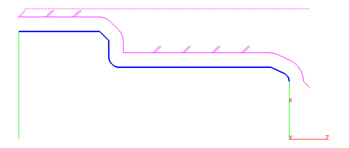
The “Peck step” setting which has been introduced for “TURN” and “BORE” operations in the Cycle Data tab of EZ-CAM v2020 is now also available for “PROFILE” cycle operations. Clearance between two pecking steps is 0.1 mm and retract / engage moves are controlled by “Engage Angle”, “Clearance”, “Withdraw Angle” and “Withdraw Distance” parameters. In addition to this standard behavior, one can now use a negative “Peck Step”. This lets the system retract along the cutting axis only (usually Z) for chip breaking. Please note that in such cases, the verified toolpath cannot show any peck steps due to the cut and retract moves overlapping each other.
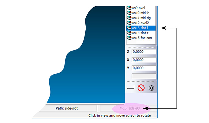
A new “MCS” button is added to the status bar of EZ-TURN so that sub-spindle and live-tool worksteps are more easily recognized by the selected UCS system.
The “Machining Side – Solid Surfaces” command has been much improved in speed and accuracy. This command should be applied when the user observes faces of the closed body having the wrong side selected after a CAD import.
While older windows versions, including first Windows 10 builds, provided options to directly set the font and size used in the application dialogs, more recent Windows 10 builds only permit users to adapt the letter size to their screen size through a global scaling factor. This change required us to modify EZ-CAM’s user interface with the help of a major update for our “WinBasic” automation language engine. In the course of this rework, we have revised and improved many of the macro dialogs, adding new functions and buttons such as the new “Select Tool” command button in the MILL / MILL Express dialogs. We have successfully tested the rework with scale factors of up to 200%.
Following a very positive reception for the ALIBRE CAD Add-In that we introduced in EZ-CAM V2020, we’ve further extended EZ-CAM’s CAD connectivity by creating a similar direct Add-In for the world-leading CAD System, SOLIDWORKS.
When single-clicked, the new plug-In command instantly transfers the model from the current SolidWorks session to the active EZ-CAM module. By hiding undesired bodies inside SolidWorks before a transfer, the user can limit the transfer to only the necessary parts of an assembly. The Add-In will be installed automatically if a local SolidWorks installation is detected during EZ-CAM v2021 installation.
EZ-CAM’s existing “Update SolidWorks” command has also been enhanced. It now automatically transfers each part of a SolidWorks assembly into a new EZ-CAM layer with ID=. And of course, EZ-CAM has been updated to also load SolidWorks v2020 files (*.SLDPRT) via its regular “File Open” command.
The existing EZ-CAM Alibre Add-on module has been further optimized for quick model update after every modification in the active Alibre session. The Add-on’s “Transfer” command instantly transfers each part in the assembly into a new EZ-CAM layer with ID=
. Further part selection in EZ-CAM is then easily handled via the “Layer Manager” introduced in EZ-CAM release v2020.
The new “Surface Tolerance” setting in the “View / Setup” dialog allows the user to specify the tessellation quality of the model imported from CAD files according to the one’s machining tolerance needs. This setting is also applied to models directly transferred from an Alibre and SolidWorks session using their respective EZ-CAM Add-In’s. By default this setting is set to 0.01 mm in metric, or 0.001 for inch mode.
The “Snap-mode” used for the currently snapped location on the screen is displayed in the status bar’s right-side message area, e.g. “Pick point [Midpoint of Line]”. This new feature is especially helpful when the snap mode is set to one of the multi-type settings such as “Snap All”.
It is now possible to apply any of the transformation commands (Translate, Move, Rotate, etc.) directly to the “WORLD” coordinate system. This offers another flexible method to set the main part origin. Alibre and Solidworks model update commands recognize the new origin set by this new method. (Please note that the “All” select command does not select the WORLD system, which can only be selected from the list box on the right side of the screen.)
The “Machining Side – Solid Surfaces” command has been much improved in speed and accuracy. This command should be applied when the user observes faces of the closed body having the wrong side selected after a CAD import.
While older windows versions, including first Windows 10 builds, provided options to directly set the font and size used in the application dialogs, more recent Windows 10 builds only permit users to adapt the letter size to their screen size through a global scaling factor. This change required us to modify EZ-CAM’s user interface with the help of a major update for our “WinBasic” automation language engine. In the course of this rework, we have revised and improved many of the macro dialogs, adding new functions and buttons such as the new “Select Tool” command button in the MILL / MILL Express dialogs. We have successfully tested the rework with scale factors of up to 200%.
The “Lettering” cycle has been updated and enhanced with some new options. The new “Select Tool” button connects to EZ-CAM’s mill tool library for tool selection. Using the “Alignment” setting enables the user to align (Left, Right, Center) the text based on the defined X and Y start coordinates. The “Font” list offers two types of single-line fonts to create efficient NC-Code. Particularly noteworthy is the addition of the “Z-Data” settings, as this greatly reduces the frequency of needing to continue to the “Advanced” machining dialog tab for further editing.
Worksteps created by the “Contour”, “Pocket” and “Face” wizards can now be edited using the same wizard dialogs. Of course, the full set of parameters and settings are always available via the “Advanced” button. The new “Select Tool” option provides access to EZCAM’s tool library, while additional toolpath and cycle options ease the usage of EZCAM’s various toolpath combinations.
While older windows versions, including first Windows 10 builds, provided options to directly set the font and size used in the application dialogs, more recent Windows 10 builds only permit users to adapt the letter size to their screen size through a global scaling factor. This change required us to modify EZ-CAM’s user interface with the help of a major update for our “WinBasic” automation language engine. In the course of this rework, we have revised and improved many of the macro dialogs, adding new functions and buttons such as the new “Select Tool” command button in the MILL / MILL Express dialogs. We have successfully tested the rework with scale factors of up to 200%.
Following a very positive reception for the ALIBRE CAD Add-In that we introduced in EZ-CAM V2020, we’ve further extended EZ-CAM’s CAD connectivity by creating a similar direct Add-In for the world-leading CAD System, SOLIDWORKS.
When single-clicked, the new plug-In command instantly transfers the model from the current SolidWorks session to the active EZ-CAM module. By hiding undesired bodies inside SolidWorks before a transfer, the user can limit the transfer to only the necessary parts of an assembly. The Add-In will be installed automatically if a local SolidWorks installation is detected during EZ-CAM v2021 installation.
EZ-CAM’s existing “Update SolidWorks” command has also been enhanced. It now automatically transfers each part of a SolidWorks assembly into a new EZ-CAM layer with ID=. And of course, EZ-CAM has been updated to also load SolidWorks v2020 files (*.SLDPRT) via its regular “File Open” command.
The existing EZ-CAM Alibre Add-on module has been further optimized for quick model update after every modification in the active Alibre session. The Add-on’s “Transfer” command instantly transfers each part in the assembly into a new EZ-CAM layer with ID=
. Further part selection in EZ-CAM is then easily handled via the “Layer Manager” introduced in EZ-CAM release v2020.
The new “Surface Tolerance” setting in the “View / Setup” dialog allows the user to specify the tessellation quality of the model imported from CAD files according to the one’s machining tolerance needs. This setting is also applied to models directly transferred from an Alibre and SolidWorks session using their respective EZ-CAM Add-In’s. By default this setting is set to 0.01 mm in metric, or 0.001 for inch mode.
A new option “Dock Spreadsheet to Right” in the “View / Customize” dialog permits the “Spreadsheet” control to be docked to the right side of the screen. With this new feature, users can make better use of wider screens and keep the Spreadsheet always visible on the right side. Naturally, the Spreadsheet can still instead be made to float and moved to a second screen.
The “Pin-down” feature that has already been available in the startup window for recently loaded part files has been added now to the four “Folder” buttons there. This enables the user to fix the display of most frequently used folders so they will be readily available.
The “Snap-mode” used for the currently snapped location on the screen is displayed in the status bar’s right-side message area, e.g. “Pick point [Midpoint of Line]”. This new feature is especially helpful when the snap mode is set to one of the multi-type settings such as “Snap All”.
Worksteps created by the “Contour”, “Pocket” and “Face” wizards can now be edited using the same wizard dialogs. Of course, the full set of parameters and settings are always available via the “Advanced” button. The new “Select Tool” option provides access to EZCAM’s tool library, while additional toolpath and cycle options ease the usage of EZCAM’s various toolpath combinations.
A new “Activate-Deactivate Worksteps” macro has been added to the “Help” menu “Toolbox” list. This macro allows single-click activation or deactivation of worksteps based on certain rules. For example: one can deactivate all worksteps below that one currently selected. This feature might be used when only certain worksteps need to be verified or simulated. In TURN mode one can also deactivate all sub-spindle worksteps for posting main-spindle work only. These are just some examples. Please note that such macros can also be assigned to certain function keys (F1-F12, via “EZCAM.INI” settings) for faster access.
It is now possible to apply any of the transformation commands (Translate, Move, Rotate, etc.) directly to the “WORLD” coordinate system. This offers another flexible method to set the main part origin. Alibre and Solidworks model update commands recognize the new origin set by this new method. (Please note that the “All” select command does not select the WORLD system, which can only be selected from the list box on the right side of the screen.)
The “Lettering” cycle has been updated and enhanced with some new options. The new “Select Tool” button connects to EZ-CAM’s mill tool library for tool selection. Using the “Alignment” setting enables the user to align (Left, Right, Center) the text based on the defined X and Y start coordinates. The “Font” list offers two types of single-line fonts to create efficient NC-Code. Particularly noteworthy is the addition of the “Z-Data” settings, as this greatly reduces the frequency of needing to continue to the “Advanced” machining dialog tab for further editing.
The “Open Surface” link type in 3D-Wizard’s “Constant-Z” finishing method has been renamed to “Zig-zag” and now can be successfully used for all tool types, including undercut tools, to shorten the machining time by eliminating rapid-over moves between consecutive z-cuts.
When manually chaining circle entities into curves, the system now checks if the connection at Z-Clear would cause collision with any of the visible surfaces. If the connection between two circles at “Z-Clear” default level would cause a collision, the circles are connected using a rapid curve link – otherwise the connection link will be of linear type. Such rapid curve links will cause the toolpath to retract to “Z-RAPID” level above the surface before continuing to the next hole to be drilled. Please note, that in order to make use of this new feature, the “Rapid Mode” curve command needs to be set to “Off” ( = Linear link if possible ). Otherwise all curve links will be of the type “Rapid” automatically.
To optimize visual toolpath check in 3D Preview, new tool properties “Cut Length” and “Shank Diameter” have been added. These settings improve the tool display and allow better clash detection for standard and custom tools. Below see the new settings in combination with the various tool types:
The new “Return to Z-Clear” option in the Z-Data section of Work Step Data allows 2.5D contouring, pocketing and zig-zag toolpaths to rapid over at “Z-Clear” height when connecting consecutive Z level passes.
3D Wizard Constant-Z methods can now perform a single z-level cut defined by the lower z-limit if the z-step is set to a big enough value.
The “Peck step” setting which has been introduced for “TURN” and “BORE” operations in the Cycle Data tab of EZ-CAM v2020 is now also available for “PROFILE” cycle operations. Clearance between two pecking steps is 0.1 mm and retract / engage moves are controlled by “Engage Angle”, “Clearance”, “Withdraw Angle” and “Withdraw Distance” parameters. In addition to this standard behavior, one can now use a negative “Peck Step”. This lets the system retract along the cutting axis only (usually Z) for chip breaking. Please note that in such cases, the verified toolpath cannot show any peck steps due to the cut and retract moves overlapping each other.
A new “MCS” button is added to the status bar of EZ-TURN so that sub-spindle and live-tool worksteps are more easily recognized by the selected UCS system.
The “Machining Side – Solid Surfaces” command has been much improved in speed and accuracy. This command should be applied when the user observes faces of the closed body having the wrong side selected after a CAD import.
While older windows versions, including first Windows 10 builds, provided options to directly set the font and size used in the application dialogs, more recent Windows 10 builds only permit users to adapt the letter size to their screen size through a global scaling factor. This change required us to modify EZ-CAM’s user interface with the help of a major update for our “WinBasic” automation language engine. In the course of this rework, we have revised and improved many of the macro dialogs, adding new functions and buttons such as the new “Select Tool” command button in the MILL / MILL Express dialogs. We have successfully tested the rework with scale factors of up to 200%.