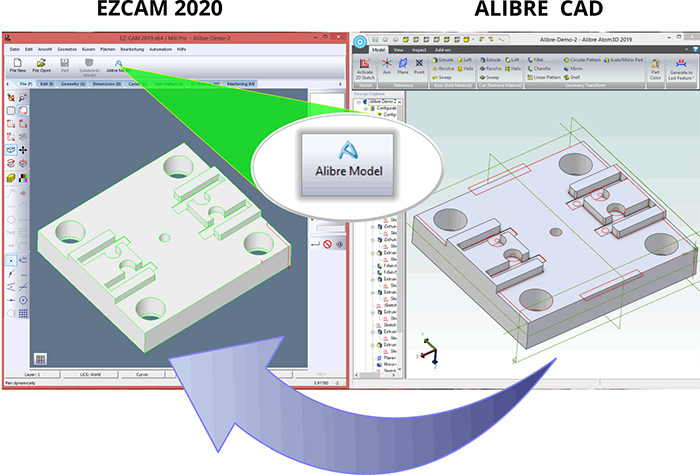
The “Update Alibre Model” command now transfers the exact model data rather than the current import/conversion process and updates previously loaded model quickly by only transferring modified faces preserving any world coordinate system changes. “3D-Wizard” Cut Surface tables are automatically modified after every Alibre model update and user-created face curves are renewed if its parent surface is modified. Alibre Design Setup is now part of EZCAM Setup so that all EZCAM users can easily see the benefits of our strong collaboration.
The legacy commands “Copy from Rhino” and “Paste from Rhino”, found on the “Edit” menu, have been renamed as “Copy Geometry” and “Paste Geometry” respectively. These commands can now be used to copy & paste selected entities including surfaces into the current layer of the same or other EZCAM windows.
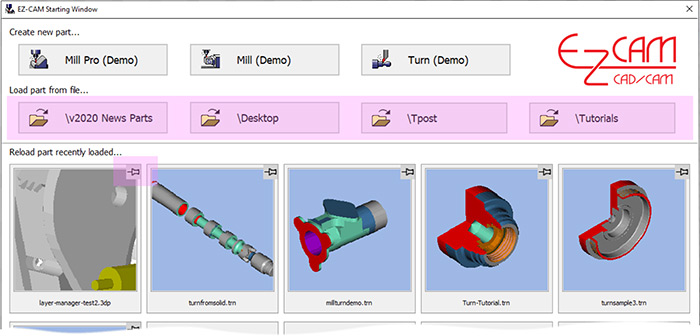
The enhanced Startup Window offers improved usability with new features. Up to four recently opened Part folders are included on top, above the recently loaded part images and both of them support tooltips displaying their full path names. “Right-click” on any recent part image in the EZ-CAM starting window shows that file in Explorer. User can pin/unpin any part file by clicking at the right top corner of its image.

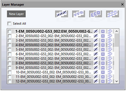
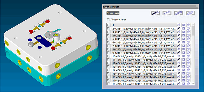
The new “Layer Manager”, located in the “Edit” menu, opens a floating spreadsheet listing all layers used in the current partfile. The first column holds the “Selection Checkbox”, followed by “Layer ID” and “Blank”, “Delete”, “Copy” commands applicable to each specific layer (row). The “Layer ID” field can be slow clicked directly to “Rename” this particular layer’s ID. “Copy” command copies entire content of that layer into the new one. At the top of the dialogs window, the “Hide All”, “Show All”, “Delete All”, “Copy All” buttons are very helpful to work with multiple selected items. The current Layer, displayed on the “Layer ID” status button at bottom of the screen is displayed in bold letters.
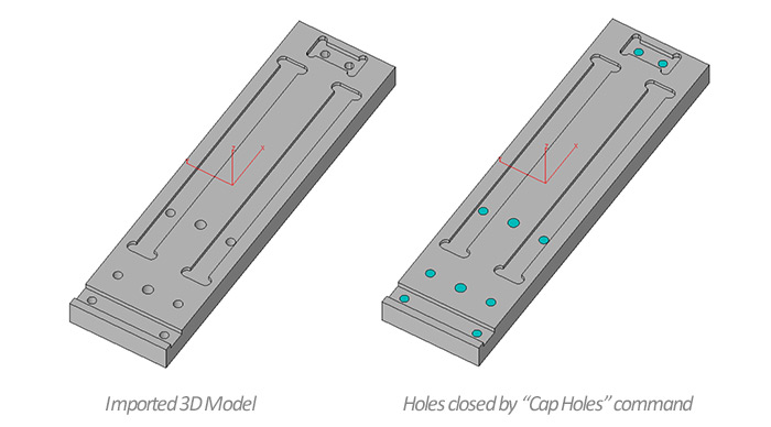
Several enhancements make it easier to work with holes in version 2020. All holes in the currently loaded model can be automatically closed by the new “Cap Holes” command located under the “Surface/Standard” menu. In addition, the “Hole Recognition” wizard now also detects circles in 2D drawings as drill paths and sets the associated “L” value (=depth) in the “Path ID” to “0”. Another enhancement now supports detection of Holes through surfaces if one of its ends is a flat circle.
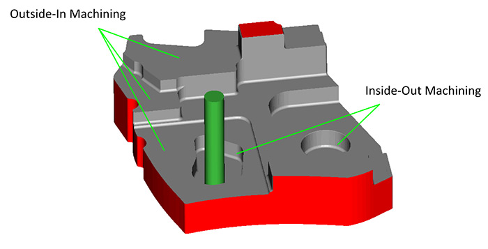
3D-Wizard Constant-Z roughing method switches outside-in option automatically for each z-level based on open/closed status of its loops.
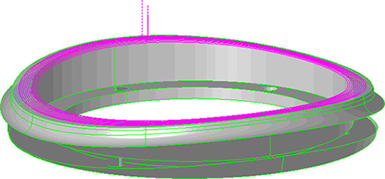
4’th axis wrapping is now supported by all projection machining cycles (Project=Facet) allowing one more finishing/roughing option for 3D-milling of surfaces. Remember though that tool will always be aligned to rotation axis center.
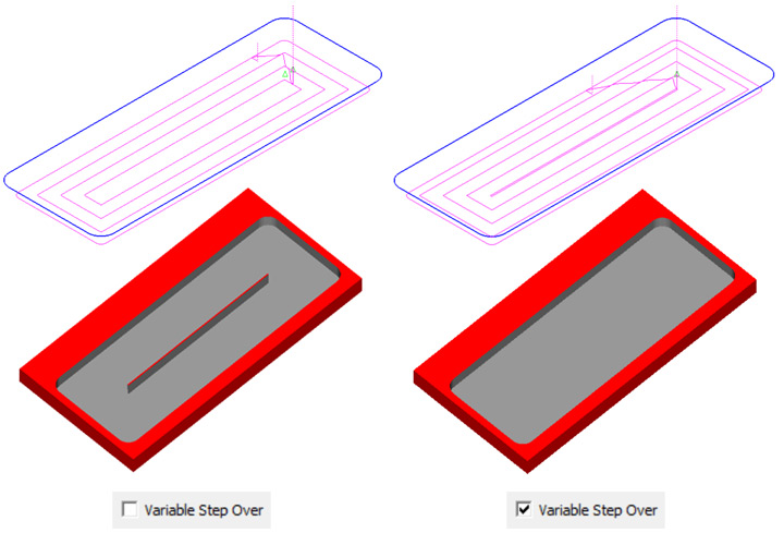
The new “Variable Step Over” option for non-HSM Pocketing operations applies adaptive step-over calculation to avoid unmachined areas. This new option is located on the “Cycle Data” tab of the machining dialogs.
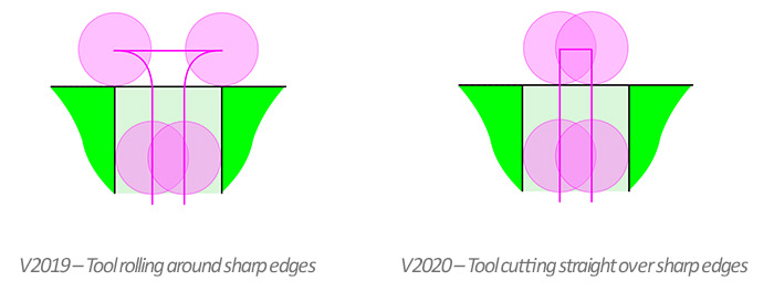
Open Edge pocketing has been completely redesigned to remove “roll around the edge” moves.
Outside-in option for 3D roughing with stock milling option has been improved to make sure toolpath start-points are always located outside of the stock.
The “Finish Path” of Zig-Zag and Pocketing cycle operations now include lead-out moves for safe rapid-up without leaving a mark on the sidewalls.
When importing CAD files with multiple solid bodies EZCAM loads the entities of each body into a new layer created with the same name of the body. Using the new “Layer Manager”, each solid body can be blanked/un-blanked or even deleted by selecting the individual layers. Alternatively, all “Edit” menu group commands such as “Move”, “Translate”, “Delete”, etc. can use these layers as discrimination filters as well.
Radius entry can be toggled to Diameter entry by clicking on letter R and vice versa making it easier to input diameter values shown in the drawings.
The “Snap All” – Point Picking option now also snaps at middle point of line/arc entity and center point of circle entity, allowing geometry creation with far less mouse clicks.

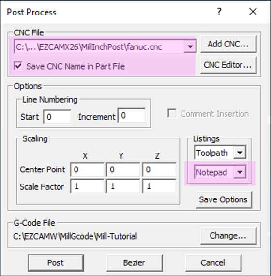
The EZ-CAM “Post” dialog is one of our main focuses in version 2020. A new listbox has been added to the “Listings” section, providing three options “None”, “EZ-DNC” and “Notepad” to be used as G-code editor. Also, recently used CNC files (post processors) are listed to save cumbersome browsing during each postprocessor change. Finally, the “Save CNC Name in Part File” option saves and reloads the last postprocessor used from the current part file.
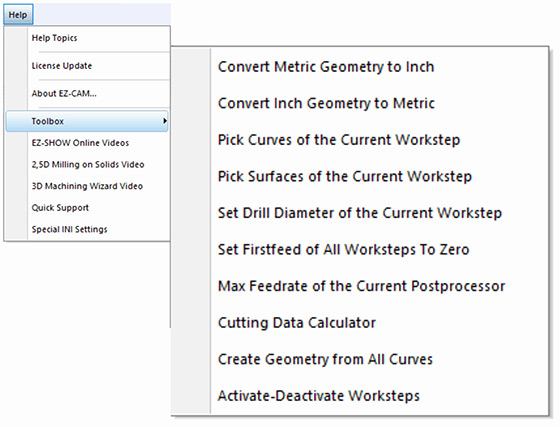
A new “Toolbox” sub-menu with some good utility functions has been added to the “Help” menu. Especially the new item to activate/deactivate worksteps with several options proves to be very helpful.
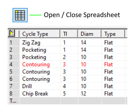
EZCAM’s famous Spreadsheet required major internal modifications to make it compatible with recent operating system updates. The new release now also displays the row of the current workstep in red (if inactive light red) for easier recognition and access. In addition, the “First Feed” parameter, important to control variable feedrate adaption for HSM pocketing operations (0=variable feedrate), has been added as a new column.
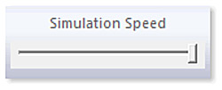
A new Simulation speed slider bar can be placed on any of the command manager tabs for quick access.
“About EZ-CAM” window in the help menu of version 2020 includes the new “Update” button for patch installation which does not require uninstall and preserves all default parameter settings and layout info. Also, it is good to know EZ-CAM version 2020 network keys can be ordered for any # of licenses.
The CAD import filter for STEP data has been modified and updated extensively. In addition, the Solidworks import has been upgraded to support latest 2019 file types.
The legacy commands “Copy from Rhino” and “Paste from Rhino”, found on the “Edit” menu, have been renamed as “Copy Geometry” and “Paste Geometry” respectively. These commands can now be used to copy & paste selected entities including surfaces into the current layer of the same or other EZCAM windows.
The enhanced Startup Window offers improved usability with new features. Up to four recently opened Part folders are included on top, above the recently loaded part images and both of them support tooltips displaying their full path names. “Right-click” on any recent part image in the EZ-CAM starting window shows that file in Explorer. User can pin/unpin any part file by clicking at the right top corner of its image.


The new “Layer Manager”, located in the “Edit” menu, opens a floating spreadsheet listing all layers used in the current partfile. The first column holds the “Selection Checkbox”, followed by “Layer ID” and “Blank”, “Delete”, “Copy” commands applicable to each specific layer (row). The “Layer ID” field can be slow clicked directly to “Rename” this particular layer’s ID. “Copy” command copies entire content of that layer into the new one. At the top of the dialogs window, the “Hide All”, “Show All”, “Delete All”, “Copy All” buttons are very helpful to work with multiple selected items. The current Layer, displayed on the “Layer ID” status button at bottom of the screen is displayed in bold letters.


Several enhancements make it easier to work with holes in version 2020. All holes in the currently loaded model can be automatically closed by the new “Cap Holes” command located under the “Surface/Standard” menu. In addition, the “Hole Recognition” wizard now also detects circles in 2D drawings as drill paths and sets the associated “L” value (=depth) in the “Path ID” to “0”. Another enhancement now supports detection of Holes through surfaces if one of its ends is a flat circle.

4’th axis wrapping is now supported by all projection machining cycles (Project=Facet) allowing one more finishing/roughing option for 3D-milling of surfaces. Remember though that tool will always be aligned to rotation axis center.

The new “Variable Step Over” option for non-HSM Pocketing operations applies adaptive step-over calculation to avoid unmachined areas. This new option is located on the “Cycle Data” tab of the machining dialogs.

Open Edge pocketing has been completely redesigned to remove “roll around the edge” moves.
Outside-in option for 3D roughing with stock milling option has been improved to make sure toolpath start-points are always located outside of the stock.

The “Finish Path” of Zig-Zag and Pocketing cycle operations now include lead-out moves for safe rapid-up without leaving a mark on the sidewalls.
When importing CAD files with multiple solid bodies EZCAM loads the entities of each body into a new layer created with the same name of the body. Using the new “Layer Manager”, each solid body can be blanked/un-blanked or even deleted by selecting the individual layers. Alternatively, all “Edit” menu group commands such as “Move”, “Translate”, “Delete”, etc. can use these layers as discrimination filters as well.

Radius entry can be toggled to Diameter entry by clicking on letter R and vice versa making it easier to input diameter values shown in the drawings.
The “Snap All” – Point Picking option now also snaps at middle point of line/arc entity and center point of circle entity, allowing geometry creation with far less mouse clicks.

The EZ-CAM “Post” dialog is one of our main focuses in version 2020. A new listbox has been added to the “Listings” section, providing three options “None”, “EZ-DNC” and “Notepad” to be used as G-code editor. Also, recently used CNC files (post processors) are listed to save cumbersome browsing during each postprocessor change. Finally, the “Save CNC Name in Part File” option saves and reloads the last postprocessor used from the current part file.

A new “Toolbox” sub-menu with some good utility functions has been added to the “Help” menu. Especially the new item to activate/deactivate worksteps with several options proves to be very helpful.

EZCAM’s famous Spreadsheet required major internal modifications to make it compatible with recent operating system updates. The new release now also displays the row of the current workstep in red (if inactive light red) for easier recognition and access. In addition, the “First Feed” parameter, important to control variable feedrate adaption for HSM pocketing operations (0=variable feedrate), has been added as a new column.

A new Simulation speed slider bar can be placed on any of the command manager tabs for quick access.

“About EZ-CAM” window in the help menu of version 2020 includes the new “Update” button for patch installation which does not require uninstall and preserves all default parameter settings and layout info. Also, it is good to know EZ-CAM version 2020 network keys can be ordered for any # of licenses.
The CAD import filter for STEP data has been modified and updated extensively. In addition, the Solidworks import has been upgraded to support latest 2019 file types.
The “Update Alibre Model” command now transfers the exact model data rather than the current import/conversion process and updates previously loaded model quickly by only transferring modified faces preserving any world coordinate system changes. “3D-Wizard” Cut Surface tables are automatically modified after every Alibre model update and user-created face curves are renewed if its parent surface is modified. Alibre Design Setup is now part of EZCAM Setup so that all EZCAM users can easily see the benefits of our strong collaboration.

The legacy commands “Copy from Rhino” and “Paste from Rhino”, found on the “Edit” menu, have been renamed as “Copy Geometry” and “Paste Geometry” respectively. These commands can now be used to copy & paste selected entities including surfaces into the current layer of the same or other EZCAM windows.
The enhanced Startup Window offers improved usability with new features. Up to four recently opened Part folders are included on top, above the recently loaded part images and both of them support tooltips displaying their full path names. “Right-click” on any recent part image in the EZ-CAM starting window shows that file in Explorer. User can pin/unpin any part file by clicking at the right top corner of its image.


The new “Layer Manager”, located in the “Edit” menu, opens a floating spreadsheet listing all layers used in the current partfile. The first column holds the “Selection Checkbox”, followed by “Layer ID” and “Blank”, “Delete”, “Copy” commands applicable to each specific layer (row). The “Layer ID” field can be slow clicked directly to “Rename” this particular layer’s ID. “Copy” command copies entire content of that layer into the new one. At the top of the dialogs window, the “Hide All”, “Show All”, “Delete All”, “Copy All” buttons are very helpful to work with multiple selected items. The current Layer, displayed on the “Layer ID” status button at bottom of the screen is displayed in bold letters.


When importing CAD files with multiple solid bodies EZCAM loads the entities of each body into a new layer created with the same name of the body. Using the new “Layer Manager”, each solid body can be blanked/un-blanked or even deleted by selecting the individual layers. Alternatively, all “Edit” menu group commands such as “Move”, “Translate”, “Delete”, etc. can use these layers as discrimination filters as well.

Radius entry can be toggled to Diameter entry by clicking on letter R and vice versa making it easier to input diameter values shown in the drawings.
The “Snap All” – Point Picking option now also snaps at middle point of line/arc entity and center point of circle entity, allowing geometry creation with far less mouse clicks.

The EZ-CAM “Post” dialog is one of our main focuses in version 2020. A new listbox has been added to the “Listings” section, providing three options “None”, “EZ-DNC” and “Notepad” to be used as G-code editor. Also, recently used CNC files (post processors) are listed to save cumbersome browsing during each postprocessor change. Finally, the “Save CNC Name in Part File” option saves and reloads the last postprocessor used from the current part file.

A new “Toolbox” sub-menu with some good utility functions has been added to the “Help” menu. Especially the new item to activate/deactivate worksteps with several options proves to be very helpful.

EZCAM’s famous Spreadsheet required major internal modifications to make it compatible with recent operating system updates. The new release now also displays the row of the current workstep in red (if inactive light red) for easier recognition and access. In addition, the “First Feed” parameter, important to control variable feedrate adaption for HSM pocketing operations (0=variable feedrate), has been added as a new column.

A new Simulation speed slider bar can be placed on any of the command manager tabs for quick access.

“About EZ-CAM” window in the help menu of version 2020 includes the new “Update” button for patch installation which does not require uninstall and preserves all default parameter settings and layout info. Also, it is good to know EZ-CAM version 2020 network keys can be ordered for any # of licenses.
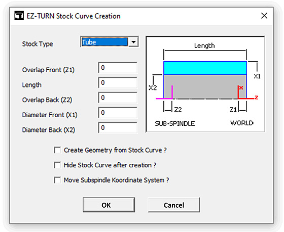
The stock curve creation dialog has been updated to support “Tube” type of workpiece.
The CAD import filter for STEP data has been modified and updated extensively. In addition, the Solidworks import has been upgraded to support latest 2019 file types.
The “Update Alibre Model” command now transfers the exact model data rather than the current import/conversion process and updates previously loaded model quickly by only transferring modified faces preserving any world coordinate system changes. “3D-Wizard” Cut Surface tables are automatically modified after every Alibre model update and user-created face curves are renewed if its parent surface is modified. Alibre Design Setup is now part of EZCAM Setup so that all EZCAM users can easily see the benefits of our strong collaboration.

The legacy commands “Copy from Rhino” and “Paste from Rhino”, found on the “Edit” menu, have been renamed as “Copy Geometry” and “Paste Geometry” respectively. These commands can now be used to copy & paste selected entities including surfaces into the current layer of the same or other EZCAM windows.
When importing CAD files with multiple solid bodies EZCAM loads the entities of each body into a new layer created with the same name of the body. Using the new “Layer Manager”, each solid body can be blanked/un-blanked or even deleted by selecting the individual layers. Alternatively, all “Edit” menu group commands such as “Move”, “Translate”, “Delete”, etc. can use these layers as discrimination filters as well.

Radius entry can be toggled to Diameter entry by clicking on letter R and vice versa making it easier to input diameter values shown in the drawings.
The “Snap All” – Point Picking option now also snaps at middle point of line/arc entity and center point of circle entity, allowing geometry creation with far less mouse clicks.

The CAD import filter for STEP data has been modified and updated extensively. In addition, the Solidworks import has been upgraded to support latest 2019 file types.
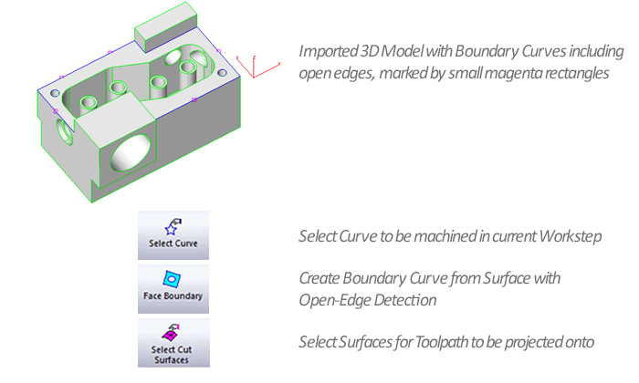
EZ-MILL Express product has been enhanced to support 2 1/2D milling of solid models and to offer starter level 3D machining. “Select Curves” (for machining) and “Face Boundary” with automatic open edge detection have been included in its “Machining” menu. 3D projection toolpaths can be created by utilizing the newly added “Select Cut” Surfaces. Copy Path command of Express won’t delete its existing path after appending the new one and all other path modify commands apply also to the curve selected by “Select Curves”.
The CAD import filter for STEP data has been modified and updated extensively. In addition, the Solidworks import has been upgraded to support latest 2019 file types.
The “Update Alibre Model” command now transfers the exact model data rather than the current import/conversion process and updates previously loaded model quickly by only transferring modified faces preserving any world coordinate system changes. “3D-Wizard” Cut Surface tables are automatically modified after every Alibre model update and user-created face curves are renewed if its parent surface is modified. Alibre Design Setup is now part of EZCAM Setup so that all EZCAM users can easily see the benefits of our strong collaboration.

The legacy commands “Copy from Rhino” and “Paste from Rhino”, found on the “Edit” menu, have been renamed as “Copy Geometry” and “Paste Geometry” respectively. These commands can now be used to copy & paste selected entities including surfaces into the current layer of the same or other EZCAM windows.
The enhanced Startup Window offers improved usability with new features. Up to four recently opened Part folders are included on top, above the recently loaded part images and both of them support tooltips displaying their full path names. “Right-click” on any recent part image in the EZ-CAM starting window shows that file in Explorer. User can pin/unpin any part file by clicking at the right top corner of its image.


The new “Layer Manager”, located in the “Edit” menu, opens a floating spreadsheet listing all layers used in the current partfile. The first column holds the “Selection Checkbox”, followed by “Layer ID” and “Blank”, “Delete”, “Copy” commands applicable to each specific layer (row). The “Layer ID” field can be slow clicked directly to “Rename” this particular layer’s ID. “Copy” command copies entire content of that layer into the new one. At the top of the dialogs window, the “Hide All”, “Show All”, “Delete All”, “Copy All” buttons are very helpful to work with multiple selected items. The current Layer, displayed on the “Layer ID” status button at bottom of the screen is displayed in bold letters.


Several enhancements make it easier to work with holes in version 2020. All holes in the currently loaded model can be automatically closed by the new “Cap Holes” command located under the “Surface/Standard” menu. In addition, the “Hole Recognition” wizard now also detects circles in 2D drawings as drill paths and sets the associated “L” value (=depth) in the “Path ID” to “0”. Another enhancement now supports detection of Holes through surfaces if one of its ends is a flat circle.

3D-Wizard Constant-Z roughing method switches outside-in option automatically for each z-level based on open/closed status of its loops.

4’th axis wrapping is now supported by all projection machining cycles (Project=Facet) allowing one more finishing/roughing option for 3D-milling of surfaces. Remember though that tool will always be aligned to rotation axis center.

The new “Variable Step Over” option for non-HSM Pocketing operations applies adaptive step-over calculation to avoid unmachined areas. This new option is located on the “Cycle Data” tab of the machining dialogs.

Open Edge pocketing has been completely redesigned to remove “roll around the edge” moves.
Outside-in option for 3D roughing with stock milling option has been improved to make sure toolpath start-points are always located outside of the stock.

The “Finish Path” of Zig-Zag and Pocketing cycle operations now include lead-out moves for safe rapid-up without leaving a mark on the sidewalls.
When importing CAD files with multiple solid bodies EZCAM loads the entities of each body into a new layer created with the same name of the body. Using the new “Layer Manager”, each solid body can be blanked/un-blanked or even deleted by selecting the individual layers. Alternatively, all “Edit” menu group commands such as “Move”, “Translate”, “Delete”, etc. can use these layers as discrimination filters as well.

EZ-MILL Express product has been enhanced to support 2 1/2D milling of solid models and to offer starter level 3D machining. “Select Curves” (for machining) and “Face Boundary” with automatic open edge detection have been included in its “Machining” menu. 3D projection toolpaths can be created by utilizing the newly added “Select Cut” Surfaces. Copy Path command of Express won’t delete its existing path after appending the new one and all other path modify commands apply also to the curve selected by “Select Curves”.

Radius entry can be toggled to Diameter entry by clicking on letter R and vice versa making it easier to input diameter values shown in the drawings.
The “Snap All” – Point Picking option now also snaps at middle point of line/arc entity and center point of circle entity, allowing geometry creation with far less mouse clicks.

The EZ-CAM “Post” dialog is one of our main focuses in version 2020. A new listbox has been added to the “Listings” section, providing three options “None”, “EZ-DNC” and “Notepad” to be used as G-code editor. Also, recently used CNC files (post processors) are listed to save cumbersome browsing during each postprocessor change. Finally, the “Save CNC Name in Part File” option saves and reloads the last postprocessor used from the current part file.

A new “Toolbox” sub-menu with some good utility functions has been added to the “Help” menu. Especially the new item to activate/deactivate worksteps with several options proves to be very helpful.

EZCAM’s famous Spreadsheet required major internal modifications to make it compatible with recent operating system updates. The new release now also displays the row of the current workstep in red (if inactive light red) for easier recognition and access. In addition, the “First Feed” parameter, important to control variable feedrate adaption for HSM pocketing operations (0=variable feedrate), has been added as a new column.

A new Simulation speed slider bar can be placed on any of the command manager tabs for quick access.

“About EZ-CAM” window in the help menu of version 2020 includes the new “Update” button for patch installation which does not require uninstall and preserves all default parameter settings and layout info. Also, it is good to know EZ-CAM version 2020 network keys can be ordered for any # of licenses.
The CAD import filter for STEP data has been modified and updated extensively. In addition, the Solidworks import has been upgraded to support latest 2019 file types.
The stock curve creation dialog has been updated to support “Tube” type of workpiece.


![]()


![]()


![]()


![]()


![]()


