EZ-MILL Pro 2016 comes with a 64-bit edition which now makes it possible to import and create 3D toolpaths for very large and complicated solid models.

Fine Tessellation option introduces a new triangulation module creating gap-free models which take up less memory but are well within chordal tolerance. Models imported with this option allow higher quality 3D toolpath creation.
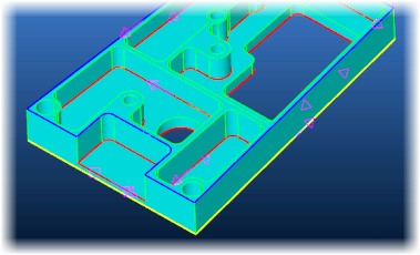
New Curve menu command “Pocket, Face, Contour Recognition” detects pockets in the currently selected UCS as curves named as “P” and colored red, faces named as “F” and colored blue, contours named as “C” and colored yellow. All paths not 100% accessible and circular paths smaller than 1 inch (12mm) diameter are omitted.
If cut step parameter of Contouring cycle is defined to create multiple passes and smooth HSM option is enabled system rounds sharp corners in all passes except the last one.

Face curve command includes a new option to automatically detect open edges.
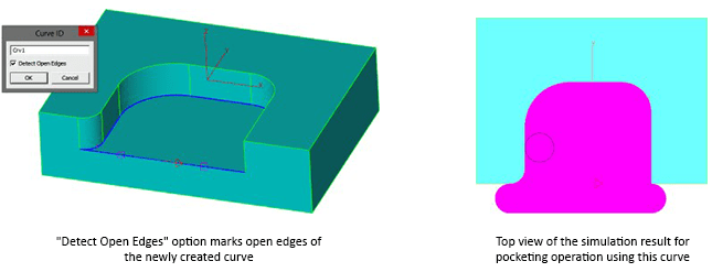
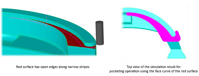
Open edge pocketing can now handle most complicated cases.
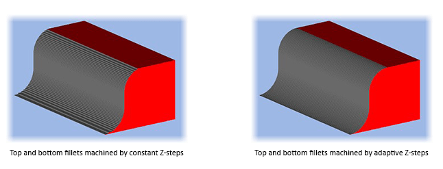
For top and bottom fillet options of draft data, Z-Step parameter becomes stepping distance along the arc.
Compute Volume command now calculates also the area enclosed by the current curve.
Autosave files are saved in “Autosave” folder in ezcam23 and session number is appended to their filenames.
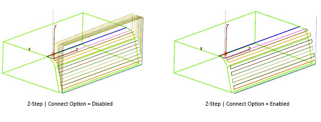
When draft parameters are applied, Connect option in Z-Data can now be activated to eliminate all rapid travels.
Calculation performance for 3d wizard methods are optimized by compressing tessellated triangle data of the 3d solid model.
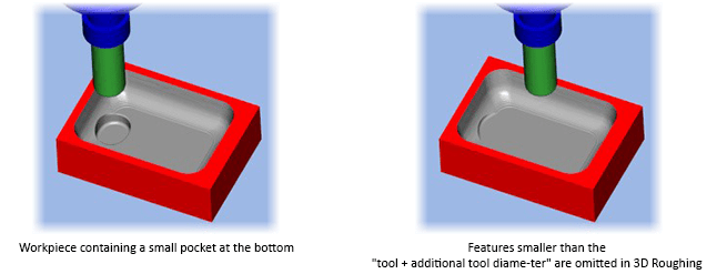
3D Roughing method offers a new parameter to set an additional tool diameter percentage which can be used to avoid the tool entering into regions which are smaller than the tool diameter plus the additional percentage. This option is essential if the tool can not plunge into the material directly and the figure does not offer enough space for alternative plunging options such as helical or zig-zag.
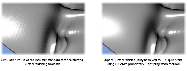
3D equidistant method with ball end tool supports now EZCAM’s proprietary “Top” projection method to get very fine surface finish. This innovative method refines the toolpath by increasing the accuracy of its points using the ana-lytical definition of the 3d model.
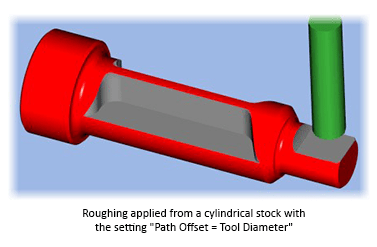
Roughing from Stock method utilizes path offset setting to extend the toolpath outside.
Outside-In option selects adequate start points in constant-z roughing levels.
If min jumps is turned on in re-roughing method toolpath passes are ordered by region minimizing rapid travels.
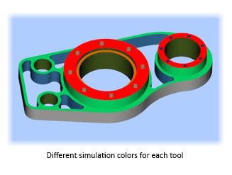
Preview simulation command uses different color for the material cut by each tool.
Simulation Setup dialog includes a new setting to select simulation stepping type as SINGLE, Z-RAPID UP, WORKSTEP or TOOL CHANGE. When system stops you can hit enter key to step or left mouse click to continue.
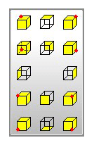
New floating toolbar with advanced viewing buttons (such as back, right front bottom, left and all other common viewing angles) can easily be activated via space bar shortcut key.
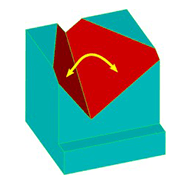
Check Angle command can now be used to display the angle between two surfaces.
Simulate Tool feature supports dynamic viewing actions (such as dynamic rotation, zooming, panning) during simula-tion.
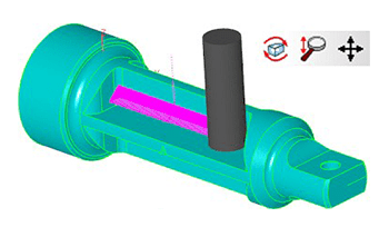
New Curve menu command “Pocket, Face, Contour Recognition” detects pockets in the currently selected UCS as curves named as “P” and colored red, faces named as “F” and colored blue, contours named as “C” and colored yellow. All paths not 100% accessible and circular paths smaller than 1 inch (12mm) diameter are omitted.

If cut step parameter of Contouring cycle is defined to create multiple passes and smooth HSM option is enabled system rounds sharp corners in all passes except the last one.

Face curve command includes a new option to automatically detect open edges.

Open edge pocketing can now handle most complicated cases.

For top and bottom fillet options of draft data, Z-Step parameter becomes stepping distance along the arc.

Compute Volume command now calculates also the area enclosed by the current curve.
Autosave files are saved in “Autosave” folder in ezcam23 and session number is appended to their filenames.
When draft parameters are applied, Connect option in Z-Data can now be activated to eliminate all rapid travels.

Preview simulation command uses different color for the material cut by each tool.

Simulation Setup dialog includes a new setting to select simulation stepping type as SINGLE, Z-RAPID UP, WORKSTEP or TOOL CHANGE. When system stops you can hit enter key to step or left mouse click to continue.
New floating toolbar with advanced viewing buttons (such as back, right front bottom, left and all other common viewing angles) can easily be activated via space bar shortcut key.

Check Angle command can now be used to display the angle between two surfaces.

Simulate Tool feature supports dynamic viewing actions (such as dynamic rotation, zooming, panning) during simula-tion.

EZ-MILL Express includes ultraHSM high-speed pocketing as standard feature. Constant material removal rate is ob-tained by feedrate optimization and circular cutting passes in combination with radial ramp in/out moves guarantee a continuous toolpath without any sharp corners. This reduces machining time and increases tool life by up to 10 times.
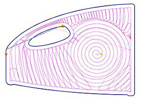
If cut step parameter of Contouring cycle is defined to create multiple passes and smooth HSM option is enabled system rounds sharp corners in all passes except the last one.

Open edge pocketing can now handle most complicated cases.

For top and bottom fillet options of draft data, Z-Step parameter becomes stepping distance along the arc.

Autosave files are saved in “Autosave” folder in ezcam23 and session number is appended to their filenames.
When draft parameters are applied, Connect option in Z-Data can now be activated to eliminate all rapid travels.

Preview simulation command uses different color for the material cut by each tool.

Simulation Setup dialog includes a new setting to select simulation stepping type as SINGLE, Z-RAPID UP, WORKSTEP or TOOL CHANGE. When system stops you can hit enter key to step or left mouse click to continue.
New floating toolbar with advanced viewing buttons (such as back, right front bottom, left and all other common viewing angles) can easily be activated via space bar shortcut key.

Simulate Tool feature supports dynamic viewing actions (such as dynamic rotation, zooming, panning) during simula-tion.

Autosave files are saved in “Autosave” folder in ezcam23 and session number is appended to their filenames.
Preview simulation command uses different color for the material cut by each tool.
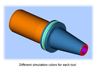
Simulation Setup dialog includes a new setting to select simulation stepping type as SINGLE, Z-RAPID UP, WORKSTEP or TOOL CHANGE. When system stops you can hit enter key to step or left mouse click to continue.
New floating toolbar with advanced viewing buttons (such as back, right front bottom, left and all other common viewing angles) can easily be activated via space bar shortcut key.

Check Angle command can now be used to display the angle between two surfaces.

Autosave files are saved in “Autosave” folder in ezcam23 and session number is appended to their filenames.
Preview simulation command uses different color for the material cut by each tool.

Simulation Setup dialog includes a new setting to select simulation stepping type as SINGLE, Z-RAPID UP, WORKSTEP or TOOL CHANGE. When system stops you can hit enter key to step or left mouse click to continue.
New floating toolbar with advanced viewing buttons (such as back, right front bottom, left and all other common viewing angles) can easily be activated via space bar shortcut key.

Compute Volume command now calculates also the area enclosed by the current curve.
XYUV profile matching using geometry lines is extended to support curves created by XY-Intersection.
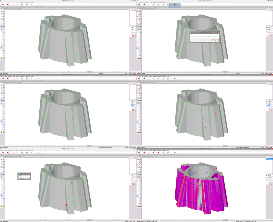
Automation Command “Auto Create XYUV” creates complete workstep just in seconds after user picks only the up-per and lower z-levels from the solid model. Thanks to the above-mentioned “profile matching by XY intersection curves” feature, upper and lower profiles are automatically matched.
Check Angle command can now be used to display the angle between two surfaces.

“Create Part Solid” option in “EZ-EDM | Stock Setup” lets 3D Preview command create solid bodies named “PartSrf1, PartSrf2, etc.”.
EZ-MILL Pro 2016 comes with a 64-bit edition which now makes it possible to import and create 3D toolpaths for very large and complicated solid models.

Fine Tessellation option introduces a new triangulation module creating gap-free models which take up less memory but are well within chordal tolerance. Models imported with this option allow higher quality 3D toolpath creation.

New Curve menu command “Pocket, Face, Contour Recognition” detects pockets in the currently selected UCS as curves named as “P” and colored red, faces named as “F” and colored blue, contours named as “C” and colored yellow. All paths not 100% accessible and circular paths smaller than 1 inch (12mm) diameter are omitted.

EZ-MILL Express includes ultraHSM high-speed pocketing as standard feature. Constant material removal rate is ob-tained by feedrate optimization and circular cutting passes in combination with radial ramp in/out moves guarantee a continuous toolpath without any sharp corners. This reduces machining time and increases tool life by up to 10 times.

If cut step parameter of Contouring cycle is defined to create multiple passes and smooth HSM option is enabled system rounds sharp corners in all passes except the last one.

Face curve command includes a new option to automatically detect open edges.

Open edge pocketing can now handle most complicated cases.

For top and bottom fillet options of draft data, Z-Step parameter becomes stepping distance along the arc.

Compute Volume command now calculates also the area enclosed by the current curve.
Autosave files are saved in “Autosave” folder in ezcam23 and session number is appended to their filenames.
When draft parameters are applied, Connect option in Z-Data can now be activated to eliminate all rapid travels.

Calculation performance for 3d wizard methods are optimized by compressing tessellated triangle data of the 3d solid model.
3D Roughing method offers a new parameter to set an additional tool diameter percentage which can be used to avoid the tool entering into regions which are smaller than the tool diameter plus the additional percentage. This option is essential if the tool can not plunge into the material directly and the figure does not offer enough space for alternative plunging options such as helical or zig-zag.

3D equidistant method with ball end tool supports now EZCAM’s proprietary “Top” projection method to get very fine surface finish. This innovative method refines the toolpath by increasing the accuracy of its points using the ana-lytical definition of the 3d model.

Roughing from Stock method utilizes path offset setting to extend the toolpath outside.

Outside-In option selects adequate start points in constant-z roughing levels.
If min jumps is turned on in re-roughing method toolpath passes are ordered by region minimizing rapid travels.
Preview simulation command uses different color for the material cut by each tool.

Simulation Setup dialog includes a new setting to select simulation stepping type as SINGLE, Z-RAPID UP, WORKSTEP or TOOL CHANGE. When system stops you can hit enter key to step or left mouse click to continue.
XYUV profile matching using geometry lines is extended to support curves created by XY-Intersection.
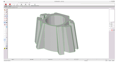
Automation Command “Auto Create XYUV” creates complete workstep just in seconds after user picks only the up-per and lower z-levels from the solid model. Thanks to the above-mentioned “profile matching by XY intersection curves” feature, upper and lower profiles are automatically matched.
New floating toolbar with advanced viewing buttons (such as back, right front bottom, left and all other common viewing angles) can easily be activated via space bar shortcut key.

Check Angle command can now be used to display the angle between two surfaces.

Simulate Tool feature supports dynamic viewing actions (such as dynamic rotation, zooming, panning) during simula-tion.

“Create Part Solid” option in “EZ-EDM | Stock Setup” lets 3D Preview command create solid bodies named “PartSrf1, PartSrf2, etc.”.


